00195376-05_SM_D1_D1i_D2_D2i_EN.pdf - 第97页
Service Work 4.3.6 Replacing the Lifting Table Stabilizer (Stabilizer Unit) [00358684-xx] PCB conveyor system Service Manual SIPLACE D1/D1i/D2/D2i 97 4.3.6 4 . 3 . 6 R e p la c in g t h e L if t in g T a b le S t a b ili…
Service Work
PCB conveyor system 4.3.5 Replacing the Lifting Table Unit [00358653]
96 Service Manual SIPLACE D1/D1i/D2/D2i
Removal
Installation
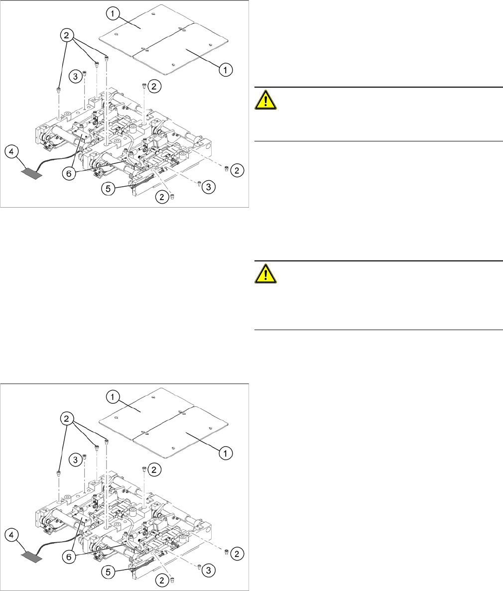
Replacing the lifting table unit (example of dual conveyor
shown)
► Move the PCB conveyor to a suitable position (e.g.
maximum width), from which you have best access to
the lifting table unit.
► Loosen the screw fastening the lifting table plate (1)
and remove the lifting table plate from the lifting table
unit.
CAUTION!
Never use a ball-head Allen wrench to loosen the screws
fastening the lifting table plates.
► Loosen the screws (2) and (3), fastening the lifting ta-
ble unit.
► Remove the cover on the conveyor conversion board
(6) and unplug the connection cable (4) from the lift-
ing table unit.
► Unplug the compressed air connection (5).
► Carefully lift the lifting table off the locating pins.
CAUTION!
Heavy machine part!
When removing the lifting table, remember it is heavy
(17.5 kg).
Replacing the lifting table unit 2 (example of dual convey
-
or shown)
► Lift the lifting table unit into the machine and position
it on the locating pins.
► Screw in the fastening screws (2) and (3).
► Reconnect to the electrical (4) and compressed air
(5) systems.
► Check the lifting table speed and the functionality of
the PCB clamping device, without the lifting table
plate.
► Set the values according to the table in "6.7.11.2 Ad-
justing the Lifting Table Speed" [ ➙ 273].
► Carefully place the lifting table plates (1) onto the lift-
ing table unit and tighten the fastening screws diago-
nally, so that the lifting table plate does not stick.
► Check the lifting table speed once the lifting table
plate has been installed. (See "6.7.11.2 Adjusting the
Lifting Table Speed" [ ➙ 273].)
Service Work
4.3.6 Replacing the Lifting Table Stabilizer (Stabilizer Unit) [00358684-xx] PCB conveyor system
Service Manual SIPLACE D1/D1i/D2/D2i 97
4.3.6
4.3.6 Replacing the Lifting Table Stabilizer (Stabilizer Unit) [00358684-xx]
Replacing the Lifting Table Stabilizer (Stabilizer Unit) [00358684-xx]
Overview
Tools and equipment required
▪ Torque wrench with plug-in ratchet [00386175-xx]
▪ Plug-in wrench 16 mm [00386177-xx]
Removal
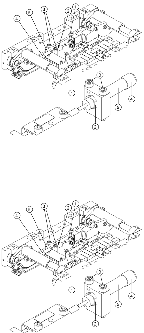
1. Actuator
2. Locknut
3. Fastening screws
4. Handle
5. Stabilizer [00358684-xx]
The stabilizer enables the lifting table to be moved gently
upwards. It prevents the PCBs from being clamped in
with too much impact.
The stabilizer consists of the shock absorber [00367737-
xx] and the damping block [00367782-xx].
► Move the PCB conveyor to the position which gives
you best access to the lifting table.
► Move the Y gantries into the area outside the PCB
conveyor.
► Switch off the machine and secure it to prevent unau-
thorized reactivation.
► Loosen the screws fastening the lifting table plate and
remove the lifting table plate from the lifting table unit.
► Loosen the two screws (3) holding the stabilizer (5).
► Undo the locknut (2) and take the stabilizer by its han-
dle (4), twisting it out of the mounting block.
Service Work
PCB conveyor system 4.3.7 Replacing the Lifting Table Solenoid Valve [03048858]
98 Service Manual SIPLACE D1/D1i/D2/D2i
Installation and adjustment
See also
6.7.11.2 Adjusting the Lifting Table Speed [ ➙ 273]
4.3.7
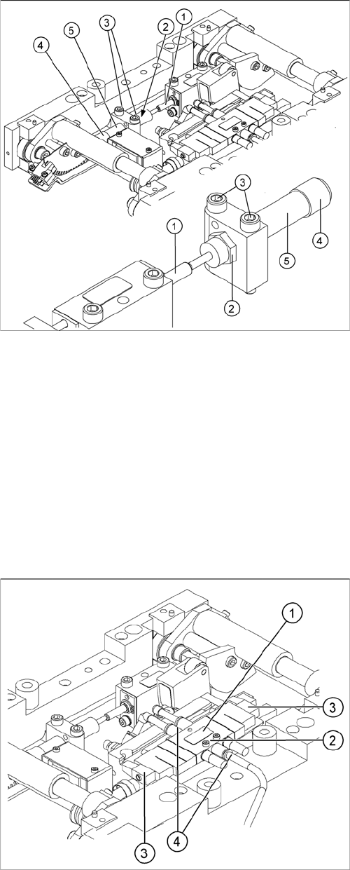
4.3.7 Replacing the Lifting Table Solenoid Valve [03048858]
Replacing the Lifting Table Solenoid Valve [03048858]
Removal/installation
► Move the PCB conveyor to the position which gives you best access to the lifting table.
► Move the Y gantries into the area outside the PCB conveyor.
► Switch off the machine and secure it to prevent unauthorized reactivation.
► Insert and twist the new stabilizer (5) until the plunger
just touches the actuator (1), so that the lifting table
can be gently moved upwards.
► Using the torque wrench:
Secure this position with the locknut (2) tightened to
8Nm.
► Check whether the stabilizer has been fixed onto the
mounting block with the locknut and that the stabilizer
plunger has a gap of approx. 0.1 mm to the actuator
(gap in untriggered mode). In this default setting, the
lifting table should move up gently.
► If this is not the case, loosen the locknut and turn the
stabilizer approx. one rotation into the mounting
block.
► Fit the lifting table plate.
► Start SITEST and move the lifting table up.
► The lifting table should move up gently i.e. you should
not hear the PCB clamping device audibly locking
into place and no clamping device error messages
should be issued.
► Check the speed of the lifting table cylinder and cor-
rect where necessary.
Legend
1. Solenoid valve
2. 2 x fastening screws for the solenoid valve
3. 2 x connection plug
4. 3x compressed air connections