00197962-01_2nd_HMI_and_Tower_Light_en - 第12页
Introduction Staff Qualifications and Training 1.3.6 SIPLACE on the World Wid e Web (WWW) 12 Assembly Instructions SIPLACE E 1.3.6 1 . 3 . 6 S I P L A C E o n t h e W o r ld W id e W e b ( W W W ) SIPLACE on the Wor ld W…

Introduction
1.3.4 Validity of Document Other Instructions
Assembly Instructions SIPLACE E 11
Always place the modules on a conductive surface (table with an ESD coating, conductive ESD foam,
ESD bag or container).
Do not bring modules near visual display units, monitors or televisions. Keep them at least 10 cm away
from the screen.
1.3.3.4
1.3.3.4 Measurements and Modifications to ESD Modules
Measurements and Modifications to ESD Modules
Measurements of the assemblies may only be taken if
▪ The measuring device has been grounded (e.g. via protective conductor) or
▪ The measuring head of the potential-free measuring device has been briefly discharged before
measurement (e.g. touching blank metal control unit housing).
► Always use an earthed soldering iron if you carry out any soldering work.
1.3.3.5
1.3.3.5 Dispatching ESD Modules
Dispatching ESD Modules
► Always store modules and components in conductive packaging (e.g. metallized plastic bags or met
-
al sleeves) and dispatch them in conductive packaging.
► If the packaging is not conductive, place the modules in a conductive envelope before packaging.
Use conductive foam rubber, ESD bags, domestic aluminum foil or paper, for example. NEVER use
plastic bags or film.
► If the module has integral batteries, ensure that the conductive packaging does not touch or short-
circuit the battery terminals and, if necessary, first cover the terminals with insulating tape or mate
-
rial.
1.3.4
1.3.4 Validity of Document
Validity of Document
This document contains service work instructions for all SIPLACE E machines.
The service work described in this manual is divided into modules and is largely identical for all machine
types:
▪ If the work required for specific machines should differ from the standard procedure, this will be in
-
dicated with reference to the machine number, series and delivery state.
▪ Diagrams should be seen as examples e.g. a machine with different paint finish does not mean that
the following information only applies to the machine type shown.
The main focus of this manual is on a description of mechanical service work.
Please refer to the circuit diagram folder for any electrical checks.
1.3.5
1.3.5 Release History
Release History
Release Changes
02/2015 Initial release

Introduction
Staff Qualifications and Training 1.3.6 SIPLACE on the World Wide Web (WWW)
12 Assembly Instructions SIPLACE E
1.3.6
1.3.6 SIPLACE on the World Wide Web (WWW)
SIPLACE on the World Wide Web (WWW)
Log into our SIPLACE
®
homepage at http://www.e-by-siplace.com.
► You can choose between the German and English versions.
The different sections contain information about our products, services and contact persons.
In addition, registered customers can also access the
SIPLACE User Group
. Here you can call up spe
-
cial information about our placement systems e.g.
▪ Technical documentation,
▪ Technical information,
▪ Spare parts lists etc.
Registration for the user group is very simple:
► Click on the Register link.
► Fill in the registration form and send it off to us.
Soon afterwards, you will receive your access authorization with USER ID and password.
1.4
1.4 Staff Qualifications and Training
Staff Qualifications and Training
Qualified or adequately trained personnel means that these people are familiar with the setting up, op
-
eration and maintenance of automatic placement systems and add-on devices and are suitably qualified,
e.g.:
▪ Have been trained, instructed or authorized to switch on and off, isolate, earth and identify electrical
circuits and system components in accordance with normal safety standards.
▪ Have been trained or instructed in the upkeep and use of appropriate safety equipment in accord
-
ance with normal safety standards.
▪ Have received first aid training.
1.5
1.5 Abbreviations
Abbreviations
Abbreviations Description
BB, BB1, BB2 Placement area, Placement area 1, Placement area 2
CO Component
COT Changeover table
COT-i Changeover table insert
C&P Collect&Place
CPP Collect&Pick&Place head
CPx Collective term for CPP, CP20, CP12 and/or CP6
CP6 SIPLACE CP6, Collect&Place head with 6 segments
CP12 SIPLACE CP12, Collect&Place head with 12 segments
CP14 SIPLACE CP14, Collect&Place head with 14 segments
ESD Electrostatic sensitive device
EMC Electromagnetic compatibility
HMI Human Machine Interface
PCB Board
P&P Pick&Place
SC Station computer
TH TwinHead
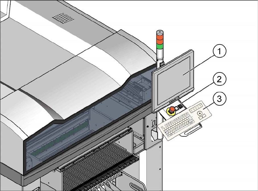
Installing a Second Human Machine Interface
Tools required
Assembly Instructions SIPLACE E 13
2
2 Installing a Second Human Machine Interface
Installing a Second Human Machine Interface
This section describes how to install a second human machine interface (HMI) at a SIPLACE E series
machine.
2.1
2.1 Tools required
Tools required
▪ M6 Hex screwdriver
▪ M4 Hex screwdriver
▪ M3 Hex screwdriver
2.2
2.2 Parts
Parts
2nd Location Human Machine Interface installation kit [03113590-xx] for SIPLACE E series
The installation kit consists of the following parts:
▪ SIPLACE E Series HMI Tower kit [03109055-xx]
1. 17-inch monitor with USB AS-1707A [03106879-xx]
2. HMI Frame kit [03111429-xx]
3. Keyboard, German Layout [00373984-xx]