00197962-01_2nd_HMI_and_Tower_Light_en - 第19页
Installing a Second Human Machine Interface 2.3.2 Step 2: Laying the Cable Branch into th e Machine Installin g the Cable Branch into the Base Machine Assembly Instructions SIPLACE E 19 ► Push the extension cable branch …
Installing a Second Human Machine Interface
Installing the Cable Branch into the Base Machine 2.3.2 Step 2: Laying the Cable Branch into the Machine
18 Assembly Instructions SIPLACE E
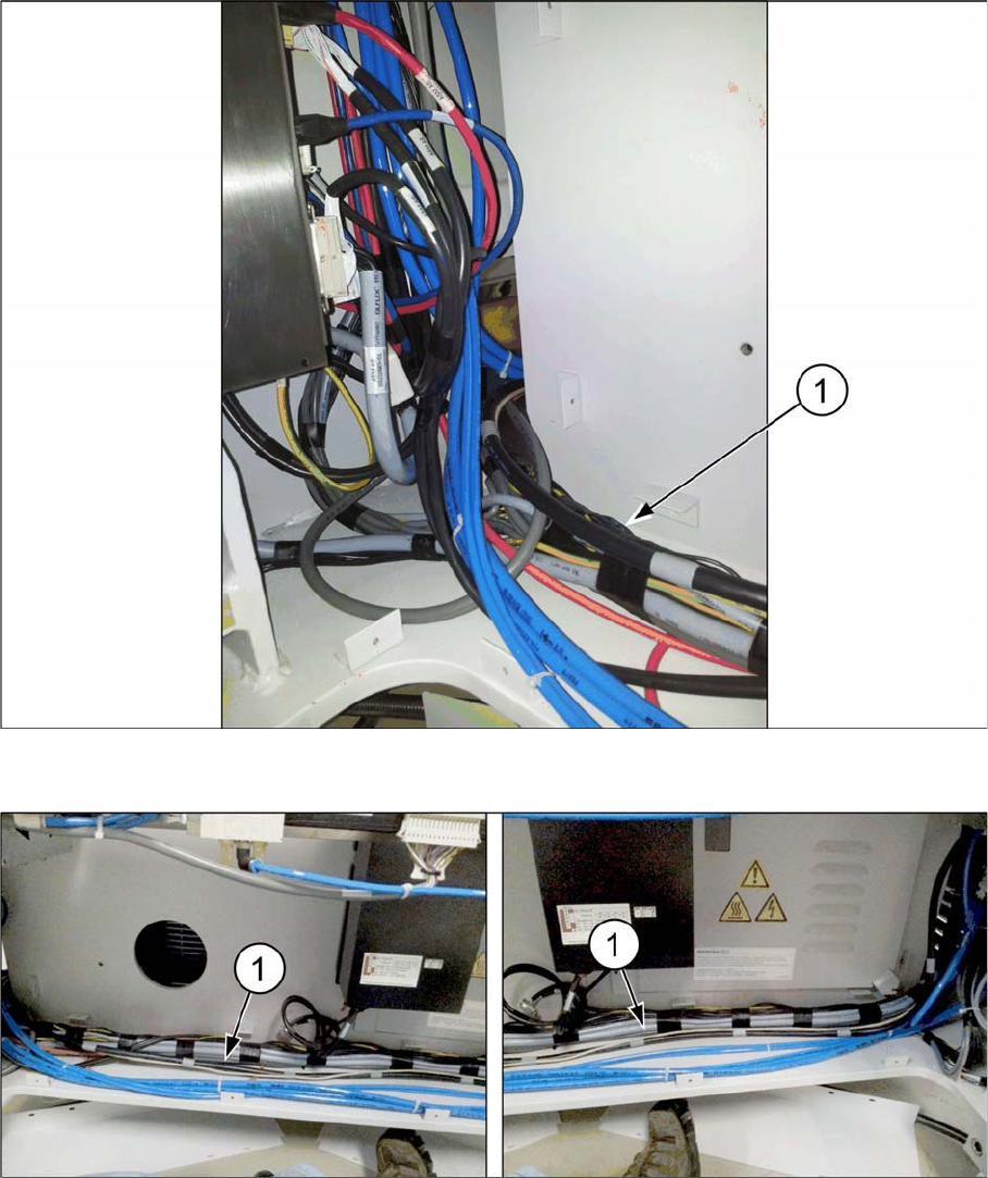
► Ensure that the extension cable branch is kept to the side of the wall (1) and does not cross the blue
pneumatic tubing.
► Lay the extension cable branch (1) alongside the other cables and the pneumatic tubing.
Installing a Second Human Machine Interface
2.3.2 Step 2: Laying the Cable Branch into the Machine Installing the Cable Branch into the Base Machine
Assembly Instructions SIPLACE E 19
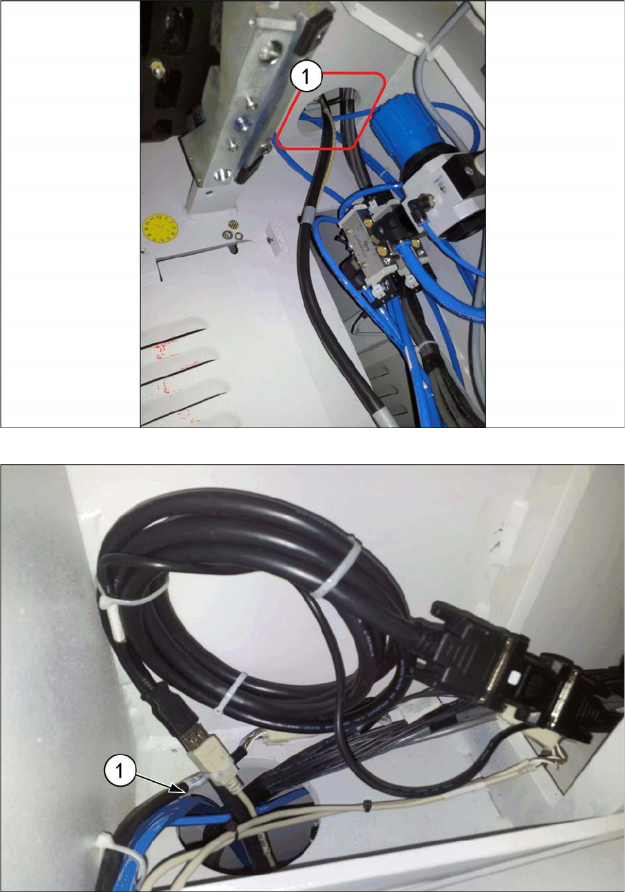
► Push the extension cable branch through the opening hole (1) on the top side.
► Roll the excess DVI extension cable in a bundle and tie it properly using cable ties.
► Tie the USB extension cable end to DVI cable (1) using a cable tie.
Installing a Second Human Machine Interface
Installing the HMI Tower Kit 2.4.1 Step 1: Mounting the Keyboard onto the HMI Frame Kit
20 Assembly Instructions SIPLACE E
2.4
2.4 Installing the HMI Tower Kit
Installing the HMI Tower Kit
2.4.1
2.4.1 Step 1: Mounting the Keyboard onto the HMI Frame Kit
Step 1: Mounting the Keyboard onto the HMI Frame Kit
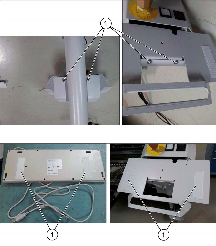
► Remove the four ISO 7380 M6x10 cap screws (1) to access the interior of the frame for routing the
keyboard cable.
► Attach the keyboard to the frame using the Velcro strips (1) provided.