00197962-01_2nd_HMI_and_Tower_Light_en - 第23页
Installing a Second Human Machine Interface 2.4.2 Step 2: Mounting the HMI Frame Kit to the Base Machine Ins talling the HMI Tower Kit Assembly Instructions SIPLACE E 23 ► Route the cable bundle at bottom of the HMI fram…
Installing a Second Human Machine Interface
Installing the HMI Tower Kit 2.4.2 Step 2: Mounting the HMI Frame Kit to the Base Machine
22 Assembly Instructions SIPLACE E
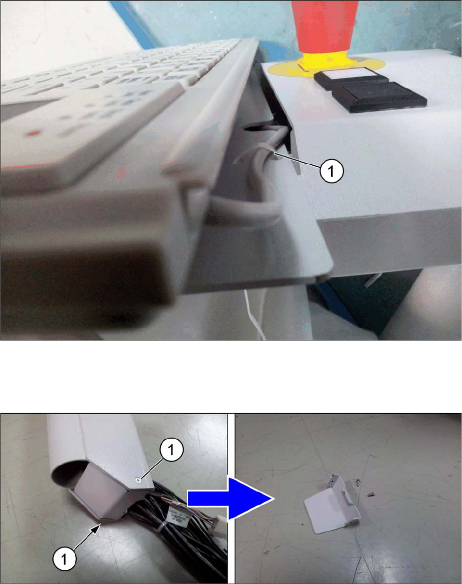
► Secure the keyboard cable to the frame using a cable tie (1).
► Replace the four ISO 7380 M6x10 cap screws that you removed earlier.
2.4.2
2.4.2 Step 2: Mounting the HMI Frame Kit to the Base Machine
Step 2: Mounting the HMI Frame Kit to the Base Machine
► Remove the two ISO 10642 M3x8 cap screws (1) at the bottom of the HMI frame.
Installing a Second Human Machine Interface
2.4.2 Step 2: Mounting the HMI Frame Kit to the Base Machine Installing the HMI Tower Kit
Assembly Instructions SIPLACE E 23
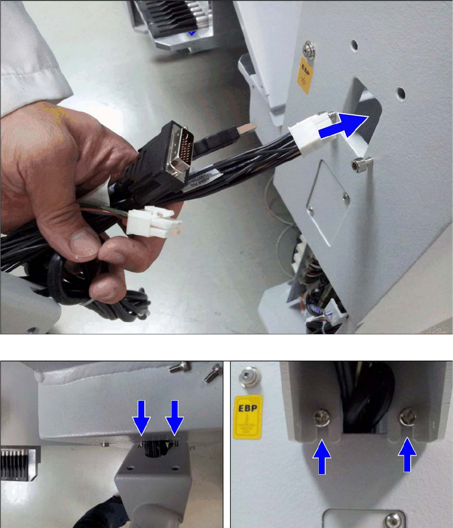
► Route the cable bundle at bottom of the HMI frame into the base machine cable inlet hole.
► Secure the two ISO 4762 M6x12 base machine screws on the outside of the base machine.
► Align and mount the HMI frame onto the two screws.
Installing a Second Human Machine Interface
Installing the HMI Tower Kit 2.4.3 Step 3: Securing the 17-Inch monitor
24 Assembly Instructions SIPLACE E
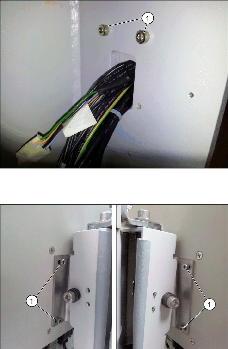
► Secure the HMI frame on the inside of the base machine using two ISO 4762 M6x20 screws (1).
► Replace the two ISO 10642 M3x8 cap screws and the bottom cover that you removed earlier.
2.4.3
2.4.3 Step 3: Securing the 17-Inch monitor
Step 3: Securing the 17-Inch monitor
► Secure the 17-inch monitor with USB AS-1707A to the HMI frame kit with four ISO 4762 M4x8 cap
screws (1).