00197962-01_2nd_HMI_and_Tower_Light_en - 第28页
Installing a Second Human Machine Interface Circuit Diagrams for the 2nd HMI In stallation Kit 2.6.1 Wiring D iagram PC to 2nd HMI Frame Kit 28 Assembly Instructions SIPLACE E 2.6 2 . 6 C ir c u it D ia g r a m s f o r t…
Installing a Second Human Machine Interface
2.4.5 Step 5: Connecting the HMI Frame Cables to the Base Machine Functional Verification After Installation
Assembly Instructions SIPLACE E 27
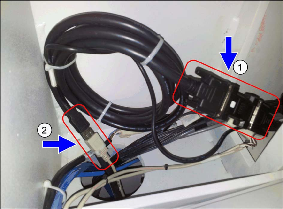
► Connect the HMI frame DVI-VGA cable male [03102206-xx] (1) to the DVI female adapter of exten
-
sion cable [03102207-xx].
► Connect the HMI frame USB A plug [03102208-xx] (2) to the USB A receptacle of the extension cable
[03102211-xx].
2.5
2.5 Functional Verification After Installation
Functional Verification After Installation
The touch screen monitor and the keyboard should be functional after machine boots up.
Installing a Second Human Machine Interface
Circuit Diagrams for the 2nd HMI Installation Kit 2.6.1 Wiring Diagram PC to 2nd HMI Frame Kit
28 Assembly Instructions SIPLACE E
2.6
2.6 Circuit Diagrams for the 2nd HMI Installation Kit
Circuit Diagrams for the 2nd HMI Installation Kit
2.6.1
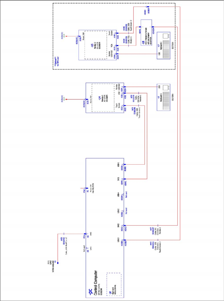
2.6.1 Wiring Diagram PC to 2nd HMI Frame Kit
Wiring Diagram PC to 2nd HMI Frame Kit
Wiring diagram PC to 2nd HMI frame kit, 03110440-010106HX9, sheet 1 of 2
Installing a Second Human Machine Interface
2.6.1 Wiring Diagram PC to 2nd HMI Frame Kit Circuit Diagrams for the 2nd HMI Installation Kit
Assembly Instructions SIPLACE E 29
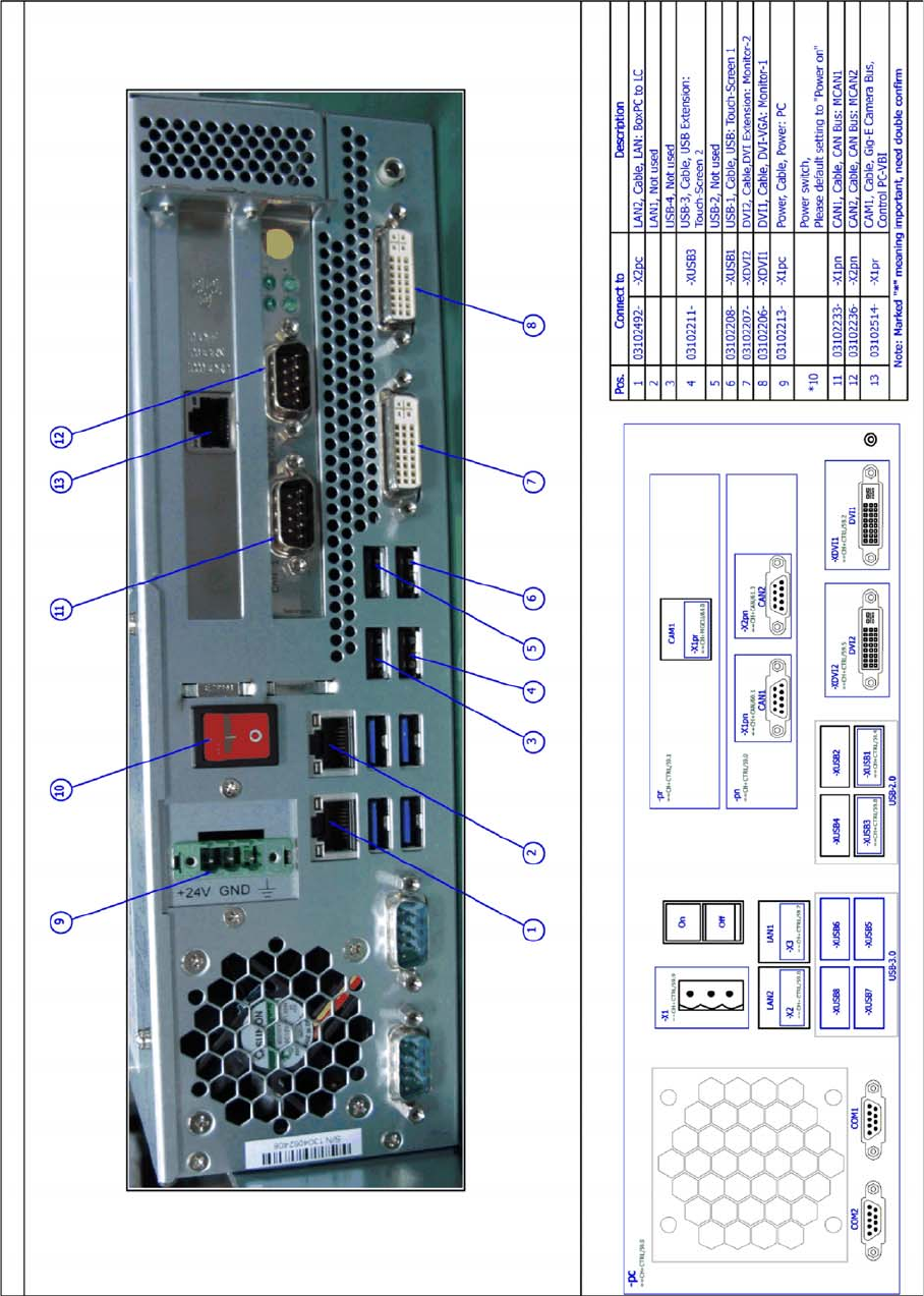
Wiring diagram PC to 2nd HMI frame kit, 03110440-010106HX9, sheet 2 of 2