00197447-01_AI_Innenraumbeleuchtung_X-Serie_S_de_en - 第36页
Brief description Required Working Time 36 Inner Illumination Innenraumbeleuchtu ng 2.4 2 . 4 R e q u ir e d W o r k in g T im e Required Working Time The complete ins tallation will take approx. 1 hour.
Brief description
Product Description
Inner Illumination Innenraumbeleuchtung 35
2
2 Brief description
Brief description
2.1
2.1 Product Description
Product Description
2.2
2.2 Scope of Delivery
Scope of Delivery
Inner illumination X S cpl. [00119739-xx]
Interior light cpl. [03107107-xx]
Mounting plate inner illumination X S cpl. [03107192-xx]
2.3
2.3 Tools and Equipment Required
Tools and Equipment Required
▪ Standard tool
▪ A cable clip or a cable tie
When activated, the inner illumination illuminates a
placement area while the machine control is being
switched off.
It is switched off in production mode.
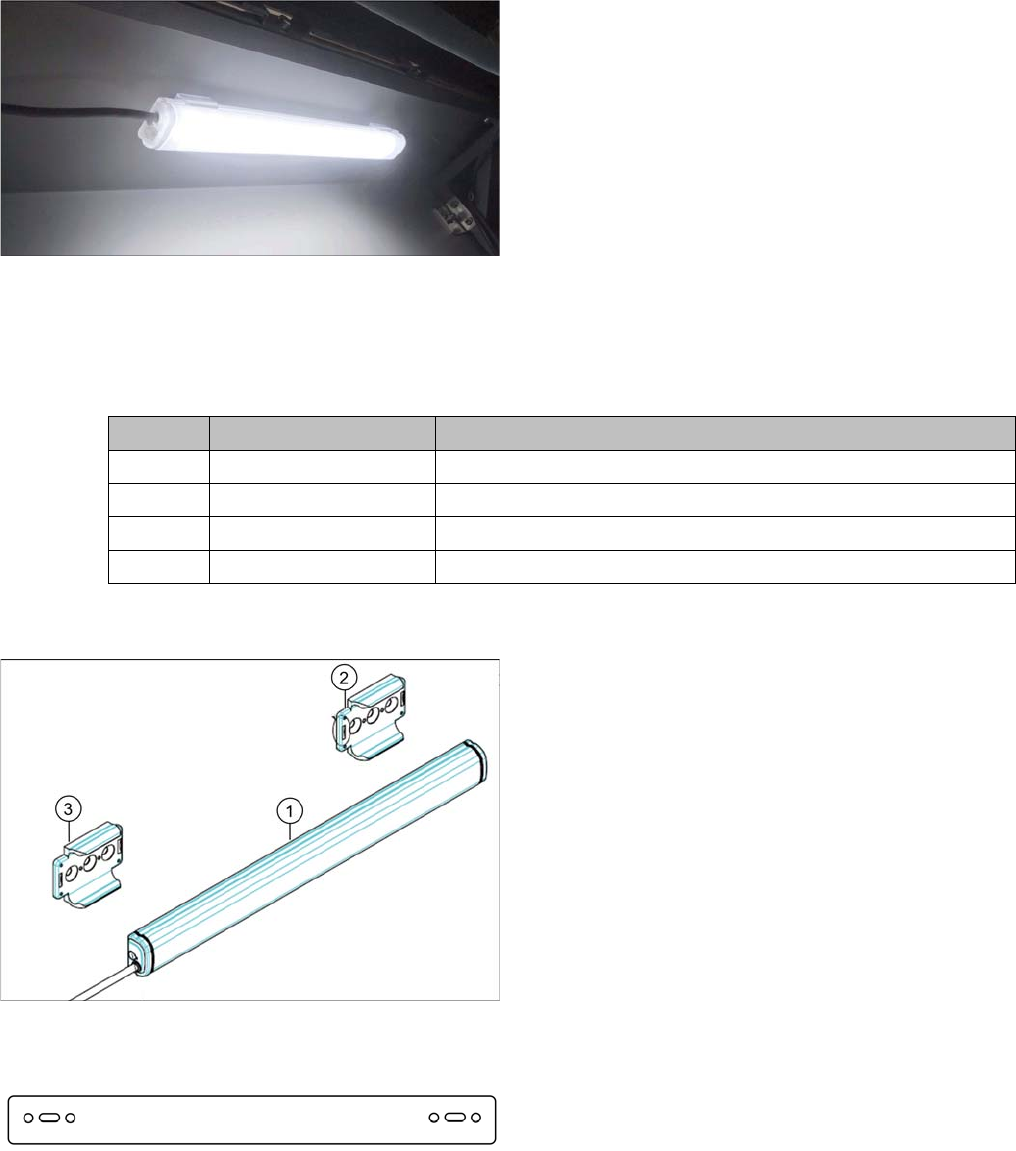
Quantity Item number Designation
1 03107107-xx Interior light cpl.
2 03082823-xx ISO 10642 - M4x10-A2-70
1 03107192-xx Mounting plate inner illumination X S cpl.
4 03093066-xx ISO 10642 - M4x6-A2-70
1. Light bar LED CLA3S-24-CD 300mm 24V
[03107105-xx]
2. Bracket SZ-310AR for CLA [03107106-xx]
3. Bracket SZ-310AR for CLA [03107106-xx]
In addition:
2 Mini MATE-N-LOK pin contact 0.30-0.89 mm2
[00354616-xx]
1 Mini MATE-N-LOK connector St 2 pole [03002124-xx]
Mounting plate inner illumination X S [03107167-xx]
Brief description
Required Working Time
36 Inner Illumination Innenraumbeleuchtung
2.4
2.4 Required Working Time
Required Working Time
The complete installation will take approx. 1 hour.
Installation
Preparatory Steps
Inner Illumination Innenraumbeleuchtung 37
3
3 Installation
Installation
3.1
3.1 Preparatory Steps
Preparatory Steps
► Switch off the machine, disconnect it from the power supply and secure it to prevent unauthorized
reactivation. Observe the instructions in section "1.2 Preparatory Work..." [ ➙ 31].
► Move the component trolley out of the machine.
See also
1.2 Preparatory Work... [ ➙ 31]
3.2
3.2 Installing the Inner Illumination
Installing the Inner Illumination
One light bar can be installed per placement area. In the following, the installation in placement area 1
is described as an example. The arrangement in placement area 2 is mirrored.
► Open the cover and fix it in a position which gives you best access for working and which ensures
that it cannot close itself on its own.
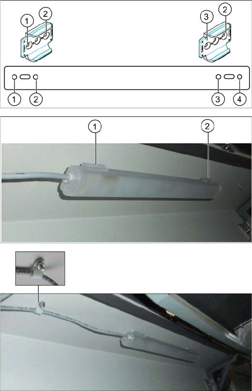
► Screw the two brackets onto the mounting plate using
the four M4x6 screws (positions 1 to 4).
► Screw the assembly consisting of brackets and
mounting plate to the provided fixation points at the
top of the machine interior (1 and 2, top left at location
1 for placement area 1, top right at location 3 for
placement area 2). Use the two M4x10 screws.
► Slide the light bar into the brackets. Make sure that
the light bar engages.
► Run the cable through the cable clip and fix the cable
clip to the provided bolt in front of the light bar.