AltaPail II Bulk Melters Product Manual.pdf - 第37页
1 3 2 1 Installation 3-6 Part 1121836_03 E 11/2014 Nordson Corporation Connect ing If cold material can be found in the hose connection ( 1), the components (2, 3) must be heated u ntil the materi al softens (approx. 70 …
1
Installation
3-5
Part 1121836_03
E 11/2014 Nordson Corporation
Connecting Hoses
Refer to the documentation that came with the hose for additional installation,
safety and troubleshooting information.
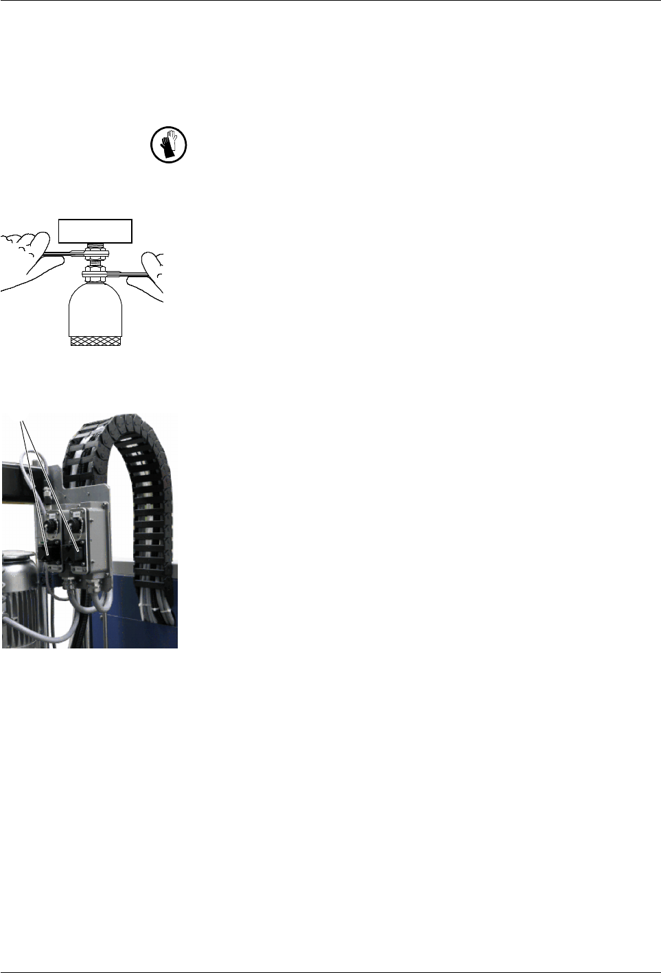
WARNING: Hot! Risk of burns. Wear heat-protective gloves.
Second Open-end Wrench
To prevent the hose connection from turning, use a second open-end wrench
when connecting and disconnecting the hose.
Electrical connection
Up to two hoses can be attached to the platen. Guide the hoses through the
hose holders to the platen and initially connect them electrically to interfaces
Hose/Applicator 1 and Hose/Applicator 2 .
1
32
1
Installation
3-6
Part 1121836_03
E 11/2014 Nordson Corporation
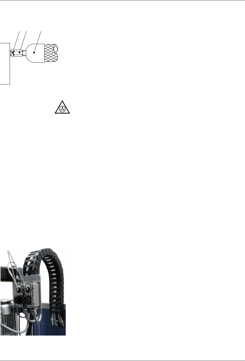
Connecting
If cold material can be found in the hose connection (1), the components
(2, 3) must be heated until the material softens (approx. 70 _C / 158 _F,
depending on material).
1. First connect the hose (3) electrically to the unit.
2. Heat the bulk melter and hose to approx. 70 _C / 158 _F.
3. Secure the hose to the unit.
NOTE: Close unused hose ports with Nordson port plugs.
Disconnecting
WARNING: To prevent serious burns, You MUST relieve the melter
pressure before disconnecting pressurized components, such as hoses, and
applicators/handguns.
Relieving pressure
1. Switch the pump Off.
2. Set selector Raise/lower platen to 0/stop.
3. Place a container under the nozzle(s) of the applicator or handgun
assembly.
4. Applicators/handguns: Activate the solenoid valve(s) electrically or
manually; or, pull the trigger on the handgun. Repeat this procedure until
no more material flows out.
5. Properly dispose of material according to local regulations.
Connecting Assembly Handguns
Connect the assembly handgun switches to receptacles Hose/Applicator 1
and Hose/Applicator 2.
When the assembly handgun is triggered (switch closed), the pump is
switched on.
Pneumatic
plate
Installation
3-7
Part 1121836_03
E 11/2014 Nordson Corporation
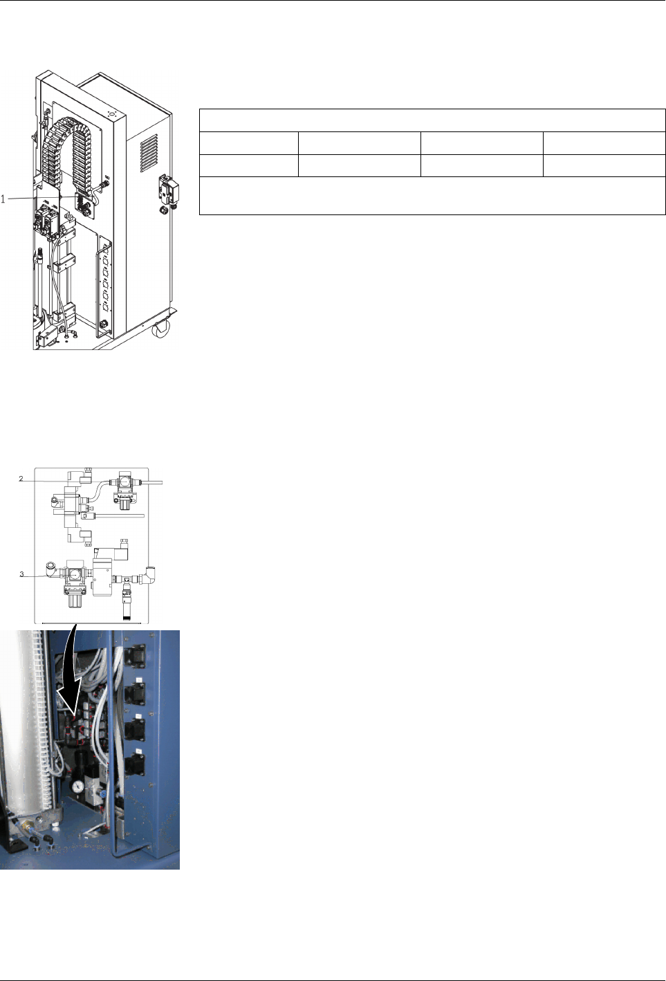
Connecting Compressed Air
Connect dry, clean and non-lubricated compressed air to the compressed air
connection (1). Dirt particles in the air may not exceed 30 m in size.
Air pressure
Min 3 bar 0.3 MPa 43.5 psi
Max 8 bar 0.8 MPa 116 psi
NOTE: A pressure restrictor valve behind the compressed air connection
limits the air pressure to 8 bar / 0.8 MPa / 116 psi
Pneumatic Plate
Also refer to pneumatics diagram.
Pressure Control Valves
CAUTION: Do not change the setting:
S
Raise pneumatic cylinder (2).
NOTE: Default pressure is 1.6 Bar / 0.16 Mpa / 23.2 PSI
S
Aerate container (3):
NOTES:
S
Default pressure is 1 Bar / 0.1 Mpa / 14.5 PSI
S
A lower pressure makes it difficult to raise the platen.