AltaPail II Bulk Melters Product Manual.pdf - 第42页
Hardware Operation 4-1 Part 1121836_03 E 11/2014 Nordson Corporation Section 4 Hardware Op eration WARNING! Allow only qual ified personnel to p erform the following ta sks. Follow the safety instructions in th is docume…

Installation
3-10
Part 1121836_03
E 11/2014 Nordson Corporation
Terminal Block XL1
Item Description Control
Options
Terminals Notes
1 Standard
input 1
Notes A
and B
-10X21:8,-10X21:9 Input activated with 10 - 30 VDC. The input is not
polarity sensitive.
2 Standard
input 2
Note A
-10X21:10,-10X21:11
Input activated with 10 - 30 VDC. The input is not
polarity sensitive.
3
Standard
input 3
Note A
-10X21:12,-10X21:13
Input activated with 10 - 30 VDC. The input is not
polarity sensitive.
4 Standard
input 4
Note A
-10X21:7,-10X21:14
Input activated with 10 - 30 VDC. The input is not
polarity sensitive.
5 Standard
output 1
Note C
-10X21:1,-10X21:2
The output is a electromechanical relay contact
rated for 2 Amps at 240 VAC or 30 VDC.
6 Standard
output 2
Note C
-10X21:3,-10X21:4
The output is a electromechanical relay contact
rated for 2 Amps at 240 VAC or 30 VDC.
7 Standard
output 3
Note C
-10X21:5,-10X21:6
The output is a electromechanical relay contact
rated for 2 Amps at 240 VAC or 30 VDC.
8 gear-to-line
0-10V input
-10X21:15,-10X21:16
Connect the positive wire to -17X21:15. Connect
the negative wire to -17X21:16. Note that the
negative input is connected to chassis (PE).
9 Pump
remote
on/off
-10X21:17,-10X21:18
Input activated with 18 - 30 VDC. The input is not
polarity sensitive. Activating the input will turn on
the motor when the remote control feature is
enabled from the user interface.
10 Pump drive
running
-10X21:19,-10X21:20
Electromechanical relay contact that indicates
motor is running when closed. Contact rated for
1.5 Amps at 240 VAC or 30 VDC.
11 24VDC
Output
-10X21:21,-10X21:22
24 V - 17x21:21
0 V - 17x21:22
Contact rating max: 24 VDC/1A
NOTE A: Input Options: Disabled, Standby, Heater Control, Pump Control and External Zone 1-8. Automatic
Standby is only available for input #1.
B: Automatic Standby is only available for input #1.
C: Output Options: Disabled, Ready, Ready-Pump On, Fault, Pail Low, Alert and Service Reminder.
Removing Bulk Melter
1. Remove the container.
2. When the bulk melter will not be used for longer periods of time, purge
with cleaning agent if necessary. Refer to page 8-6, Purging with
Cleaning Agent.
3. Wipe off sealing ring and clean melting plate. Refer to page 8-6, Cleaning
Melting Plate.
4. Disconnect all lines to the bulk melter, and allow bulk melter to cool.
Bulk Melter Disposal
When your Nordson product has exhausted its purpose and/or is no longer
needed, dispose of it properly according to local regulations.

Hardware Operation
4-1
Part 1121836_03
E 11/2014 Nordson Corporation
Section 4
Hardware Operation
WARNING! Allow only qualified personnel to perform the following tasks.
Follow the safety instructions in this document and all other related
documentation.
Hardware Operation
4-2
Part 1121836_03
E 11/2014 Nordson Corporation
First Time Startup
The initial startup is a 4-step process.
Step Description Refer to Page
1 Switch the Main Power On. 4-2
2 Following the handling instructions that came with the PUR
adhesive container, place the container in place and remove
the cover.
3 Raise/Lower the Platen 4-3
4 Purge any material in the system. 4-6
The following sections detail each procedure in greater detail.
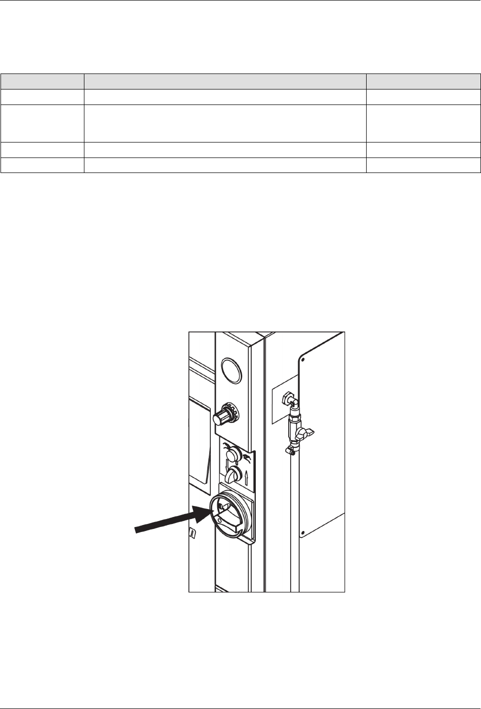
Switching the Melter On/Off
S
To switch the melter On, turn the Main Power Switch clockwise (to the
right)
S
To switch the melter Off, turn the Main Power Switch counter clockwise
(to the left)
Main Power Switch
NOTE: Before initial startup and every time the container is replaced,
remove residue and lubricate the platen sealing ring (Refer to page 8-2,
Processing Materials for lubricant). Do not use sharp tools.