GD450 说明书(中英文版) - 第90页
- 9 0 - 图 6-6 (设置检测点) Pix 6-6(setup the inspection spot) 7. 点击定置模板后, 如图 6-7 , 显示检测点序号和坐标。 如果还有需要设置检测点, 则点 击增加记录,进行如上第三步以后的操作。 After clicking “ 定置模板 ” (temp late customization) button, it will show the item and positionin…
- 89 -
Pix 6-5(template setting)
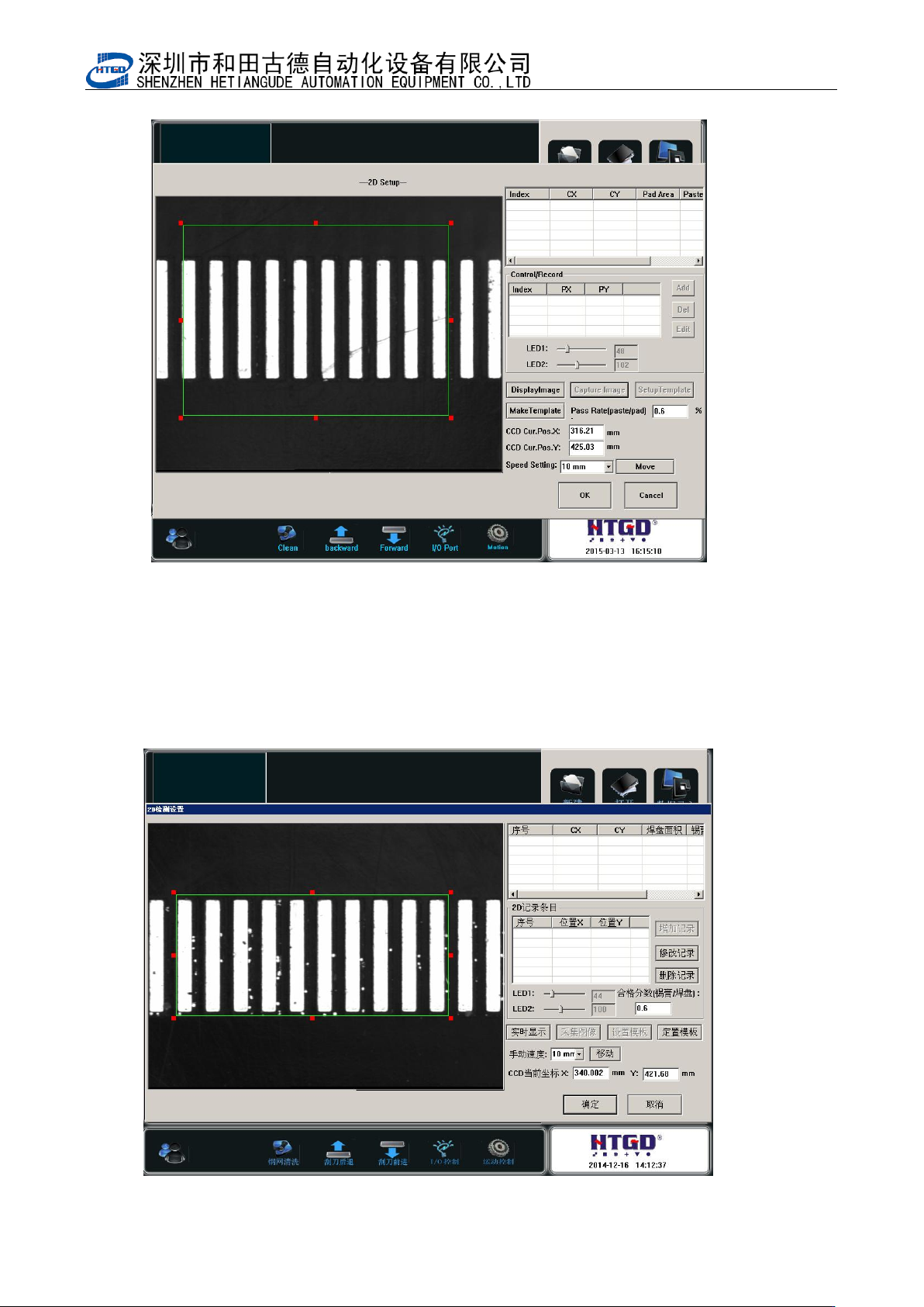
6. 如图 6-6,设置好检测点后,点击定置模板。
Click “定置模板”(template customization) button after setting the inspection spot. See
pix 6-6.
- 90 -
图 6-6(设置检测点)
Pix 6-6(setup the inspection spot)
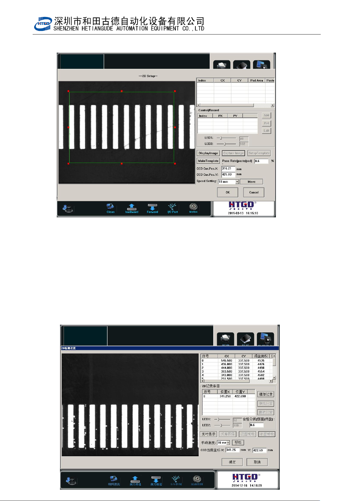
7. 点击定置模板后,如图 6-7,显示检测点序号和坐标。如果还有需要设置检测点,则点
击增加记录,进行如上第三步以后的操作。
After clicking “定置模板”(template customization) button, it will show the item and
positioning of the inspection spot. If operator needs to setup more inspection spot,
please click “增加记录”(add record) button. And do the operations from step 3 to step
- 91 -
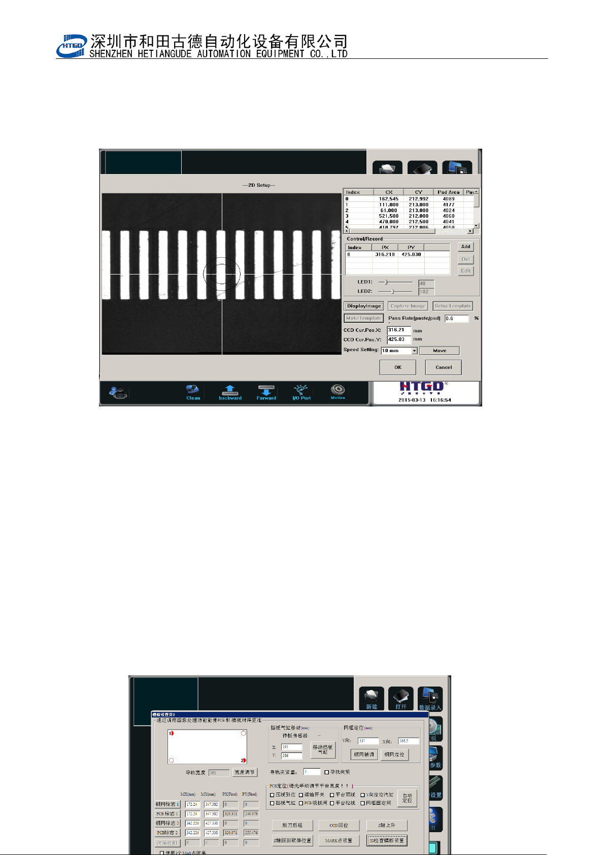
图 6-7(检测点)
Pix 6-7(inspection spot)
8 输入要检测的 PCB 上锡膏可以合格通过的覆盖率,本机器设定焊膏覆盖焊盘的面积在
60%以上即满足质量要求(即合格分析锡膏/焊盘:0.6)。
Input the cover rate which can pass the inspection for the solder paste printed on the PCB. If
there are above 60% solder paste printed on the bonding pad, then it can meet the printing
quality requirement. (The qualified rate: solder paste/bonding pad: 0.6)
9 如图 6-7,点击确定,完成 2D 检测点的建立、增加的动作及参数设置。
Click “确定”(ok)button, then finish the build of 2D inspection spot, movement add and
parameter setting. See pix 6-7.
10 点击确定,保存已更改的数据。如图 6-8
Click “确定”(ok)button to save the changed data. See pix 6-8.Pix 6-8(click
“确定” (ok)button after setting the 2D inspection)