Integration Stanzförderer.pdf - 第11页
Retrofit Instructions - Special Design for Integrating the Punching Die Feeder for t he HF series 11/2004 Edition 11 2 Retrofit Instructions - S pecial Design for Integrating the Punching Die Feeder for th e HF series 2.…
Nachrüstanleitung SOKO Integration Stanzförderer HF-Serie
Ausgabe 11/2004
10
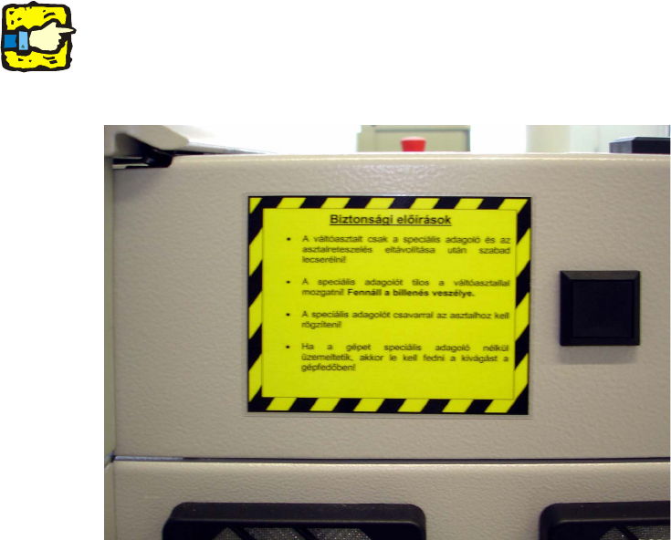
: Bringen Sie ein Hinweisschild an, das auf die mechanische Sperre des BE-Wagens hinweist.
1
Warnschilder bzgl. Quetschgefahr im Stanzbereich des Förderers liegen im Verantwortungsbe-
reich des Kunden. 1
1
1
1
1
1
1
1
1
1
1
1
1
1
Retrofit Instructions - Special Design for Integrating the Punching Die Feeder for the HF series
11/2004 Edition
11
2 Retrofit Instructions - Special Design
for Integrating the Punching Die
Feeder for the HF series
2.1 Restrictions
– The feeder must be bolted to the component table, otherwise it would not be possible to fix the
pick-up position. There is also a risk of accident if the feeder is not fixed.
– The feeder and the component table lock must both be removed before the component table
is replaced.
– If the modified feeder area is operated without a special feeder, then the customer is respon-
sible for providing a suitable hand guard.
– The risk of crashing in the event of a feeder fault cannot be excluded since communication be-
tween the feeder and machine is lost.
– No "flat" component tapes can be used in the feeder area of the special feeder since the re-
ducer has to be removed from the tape removal channel.
– The special feeder can only be set up at location 2, track 49-90.
– The feeder is not supported by SIPLACE Pro and can only be described as a linear feeder with
a suitable offset.
– Siemens L&A does not guarantee that the feeder will work correctly.
2
2
2
2
2
2
2
2
2
2

Retrofit Instructions - Special Design for Integrating the Punching Die Feeder for the HF series
11/2004 Edition
12
2.2 Safety instructions
WARNING
The safety instructions from the “Operational safety” chapter of the user manual and servicing in-
structions take precedence over these instructions. 2
The SIPLACE placement machines are supplied with mains voltage.
Consequently parts of these systems carry dangerous voltages! This voltage is present at certain
modules inside the machine base, even when the machine is switched off at the main power
switch. 2
Incorrect handling of the placement machine or touching live parts of the machine can result in
death or severe injury, and considerable damage to equipment. 2
BEFORE starting any work, shut down the operating system correctly, then switch the machine
OFF at the main power switch and disconnect from the main power supply. In addition, the com-
pressed air supply must be switched off at the compressed air unit's main valve in the machine
base and vented by actuating the needle valve on the compressed air unit. 2
There is DANGER for heart pacemaker wearers in the vicinity of the linear motors, as described
in detail in the "Special safety instructions for working in the vicinity of strong magnetic fields" sec-
tion of the user manual and service manual. 2
Always follow the accident prevention regulations, DIN or other standards and special safety rules
applicable in your country.
Pay attention to the information concerning residual voltages in the Operational Safety chapter.
Follow the ESD regulations as described in the operational safety section of the operating instruc-
tions.
During the retrofit, always secure the machine to prevent access by other people and to prevent
it being switched on again. The procedure is described in the “Locking the machine…” section of
the user manual.
Working with the SITEST program further increases the risk of accident.
The SITEST program must only be used by authorized and trained personnel. 2
2
2.2.1 Definition
2
PLEASE NOTE 2
2