QP132三级参考手册.pdf.pdf - 第130页
18. Press [AUTO] to transmit the program to the PMC. 19 . Press [SET] → [PROPER] → ID No. → [PM] → select the module → [FINISH] → [Part Camera] → [CALIB CNTR] → [In turn meas] → [EXECUTE] → Enter a starting PM No. and fi…
7. Attach double sided tape to the board.
PCB PAM BOARD-1 (white face color)
Set the end of the tape approximately 17.0 mm from the right edge
of the board. Apply to the end in the Y-direction.
8. Press [SET] → [PROPER] → [MAIN UNIT] → [MARK CAMERA] →
[RSLTION/CNTR] to display the image.
9. Align the crosshairs of the real image with the T-mark positioned
between the SS-rail and return conveyor.
10. Press [SET] → [PROPER] → ID code → [MAIN] → [MARK CAMERA] →
[T MARK] → [MEASURE] → START.
11. Repeat a few times to stabilize the value.
12. Attach a 1.3 diameter nozzle to holders A, B, C and D.
13. Press [PROGRAM] → [CHANGE] → Select program PORP_8 to the
foreground.
14. Press [AUTO] to transmit the program to the PMC.
15. Press [SET] → [PROPER] → ID No. → [PM] → select the module →
[FINISH] → [Part Camera] → [CALIB CNTR] → [In turn meas] →
[EXECUTE] → Enter a starting PM No. and final PM No. → START.
16. Attach a 1.3 diameter nozzle to holders E (A) and F (D).
17. Press [PROGRAM] → [CHANGE] → Select program to PORP_17 to the
foreground.
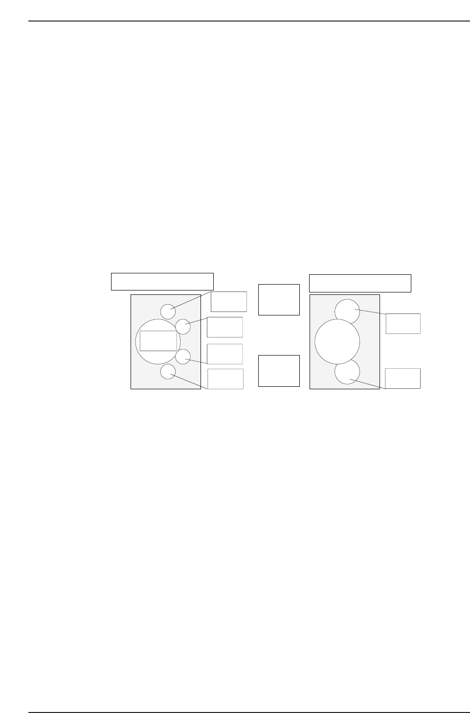
↑
QP132T11001
View from top of X-axis head
Nozzle A
Nozzle B
Nozzle C
Nozzle D
Nozzle E
Nozzle F
(M/C rear)
↓
(M/C front)
View from top of X-axis head
Q gear
Chapter 11 11.1 PAM
Edition 1.1 11-2 QP-132 Level 3 Tutorial

18. Press [AUTO] to transmit the program to the PMC.
19. Press [SET] → [PROPER] → ID No. → [PM] → select the module →
[FINISH] → [Part Camera] → [CALIB CNTR] → [In turn meas] →
[EXECUTE] → Enter a starting PM No. and final PM No. → START.
20. Press [SET] → [PROPER] → ID code → [PM → [SET] → [PARTS
CAMERA] → [T MARK] → [MEASURE] → START.
21. Repeat a few times to stabilize the value.
22. Load one board on the machine and execute PAM production.
23. When Manipulator sets the board on the pallet in the IN-Transfer
Loader, press [CLEAR OFF] and produce only one board.
24. Transmit the Proper data to F4G/FujiCam. Copy the Proper data to a
floppy disk.
25. Set the completed board in the DT451.
26. Boot the software, “DT-651 Placement Position Auto-calibration system”.
27. Press [F1] to zero set.
28. Press [F1] to select the program PAM_ALL.PGO.
29. Press START to measure the placement.
30. Select [Renew Proper].
31. Insert the floppy disk and select the Proper from the floppy disk.
32. Press [OK] to rewrite the Proper data.
33. Press [FILE] to save the measured data to the floppy.
34. Insert the floppy disk to the PC.
35. Copy the sequence on the measured data to the QP132_1Cpk.xls for the
offset calculation.
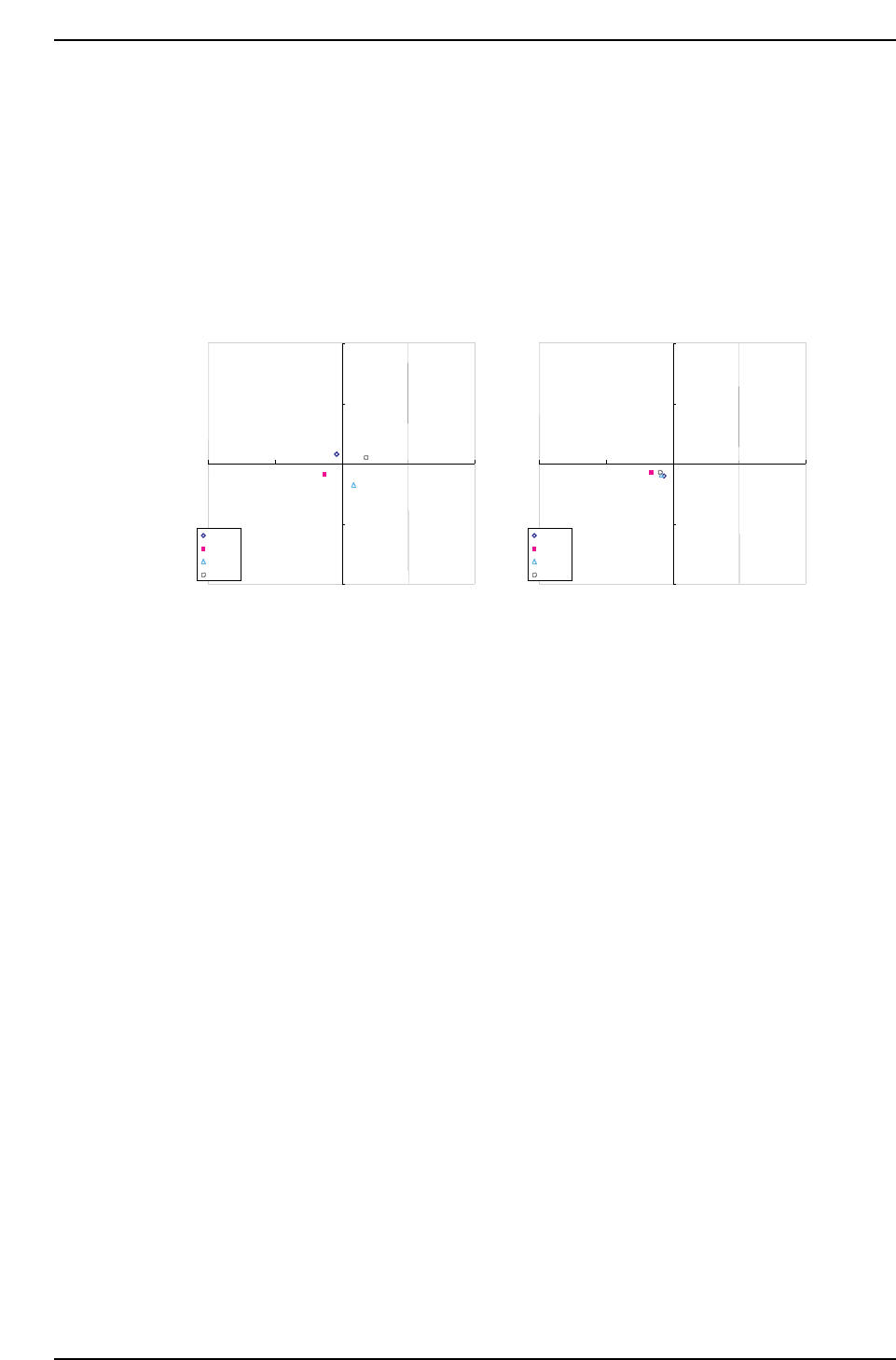
Note: DXC, DXY, nozzle center offset value, will be displayed on the right side of the chart.
The adjacent chart is the current arrangement.
Chapter 11 11.1 PAM
Edition 1.1 11-3 QP-132 Level 3 Tutorial
36. Copy the renewed Proper data from floppy to F4G/FujiCam and add the
center offset value of XLS.
37. Check the 3σ value.
38. Transmit the Proper data to the machine and reboot.
39. Repeat procedures 2 ~ 38.
Note: If a particular nozzle has poor accuracy, other causes may need to be investigated.
40. Repeat the procedure until:
CP: more than 1.7
CPK: more than 1.4
AVE: less than ± 20 µm
3σ: less than 100
Note: If the accuracy does not satisfy these conditions, contact FUJI.
ZC Automatic measurement for rotation center
-200
-100
0
100
200
-200 -100 0 100 200
0¡
90¡
180¡
270¡
ZC Rotate center with offset
-200
-100
0
100
200
-200 -100 0 100 200
0¡
90¡
180¡
270¡
QP132T11002
Chapter 11 11.1 PAM
Edition 1.1 11-4 QP-132 Level 3 Tutorial