QP132三级参考手册.pdf.pdf - 第37页
Notes: Chapter 1 1.3 Measuring In Manipulator Proper Data and Adjustment Edition 1.1 1-10 QP-132 Level 3 T utorial
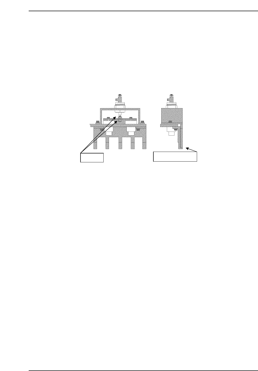
1.3.5 PCB Retaining Cylinder for the Manipulator
1. Press [SET] → [MANUAL] → [I/O] → [STANDARD I/O] → [OUTPUT]
and use Y050 PCBCD UP to raise the manipulator.
2. Loosen the two (2) black nuts attached to the cylinder.
3. Rotate the nuts, and move the jaw upwards. Then, lower the jaw to a
position where a 0.5 mm feeler gauge can fit in.
4. Remove the feeler gauge and slightly lower the jaw. Then lock it.
5. Ensure that the feeler gauge cannot fit in.
6. Clamp the 0.8 mm feeler gauge, and ensure that it clamps properly.
Adj. nuts
Place feeler gauge
QP132T1007
Chapter 1
1.3 Measuring In Manipulator Proper Data and Adjustment
Edition 1.1 1-9 QP-132 Level 3 Tutorial

Notes:
Chapter 1
1.3 Measuring In Manipulator Proper Data and Adjustment
Edition 1.1 1-10 QP-132 Level 3 Tutorial

1.4 Training Evaluation
Circle the most appropriate answer from the list below.
(1) To replace MX or MY motor, boot up the machine in:
a. mechanical check mode.
b. normal mode.
c. normal mode with Proper data setting.
(2) To measure PCB Pickup Position MX, move the axis by:
a. hand.
b. inching.
c. command.
(3) To replace the MY motor, set the velocity gain:
a. lower.
b. higher.
c. the same value.
(4) To measure PCB Landing Position MX FDW, adjust the distance between
the right edge of the reference jaw and left edge of the pallet to:
a. 1.2 mm.
b. 1.3 mm.
c. 1.4 mm.
(5) To adjust PCB Retaining Cylinder for Manipulator, which tool is
required?
a. 0.5 mm feeler gauge
b. 0.8 mm feeler gauge
c. 1.6 mm PCB
Chapter 1 1.4 Training Evaluation
Edition 1.0 1-11 QP-132 Level 3 Tutorial