QP132三级参考手册.pdf.pdf - 第44页
7. Press [SET] → [PROPER] → [MAIN UNIT] → [ETC.] → [MANIPULATE] → [AXIS CHG P0/(AXIS CHG MX9)] → [PK DIRECT PO] → [SET] to record the value in Proper data. 2.2.3 PCB Pickup Position PO (Rotate-Loading) 1. Press the EMERG…

2.2 Measuring Out Manipulator Proper Data
and Adjustment
2.2.1 PCB Placing Position PO
1. Press the EMERGENCY STOP button to shutdown the 200V.
2. Move the PO-axis to the out-conveyor.
3. Adjust the speed controller so that the manipulator descends slowly.
4. Press [SET] → [MANUAL] → [I/O] → [STANDARD I/O] → [OUTPUT]
and Y071 PCB UL DOWN.
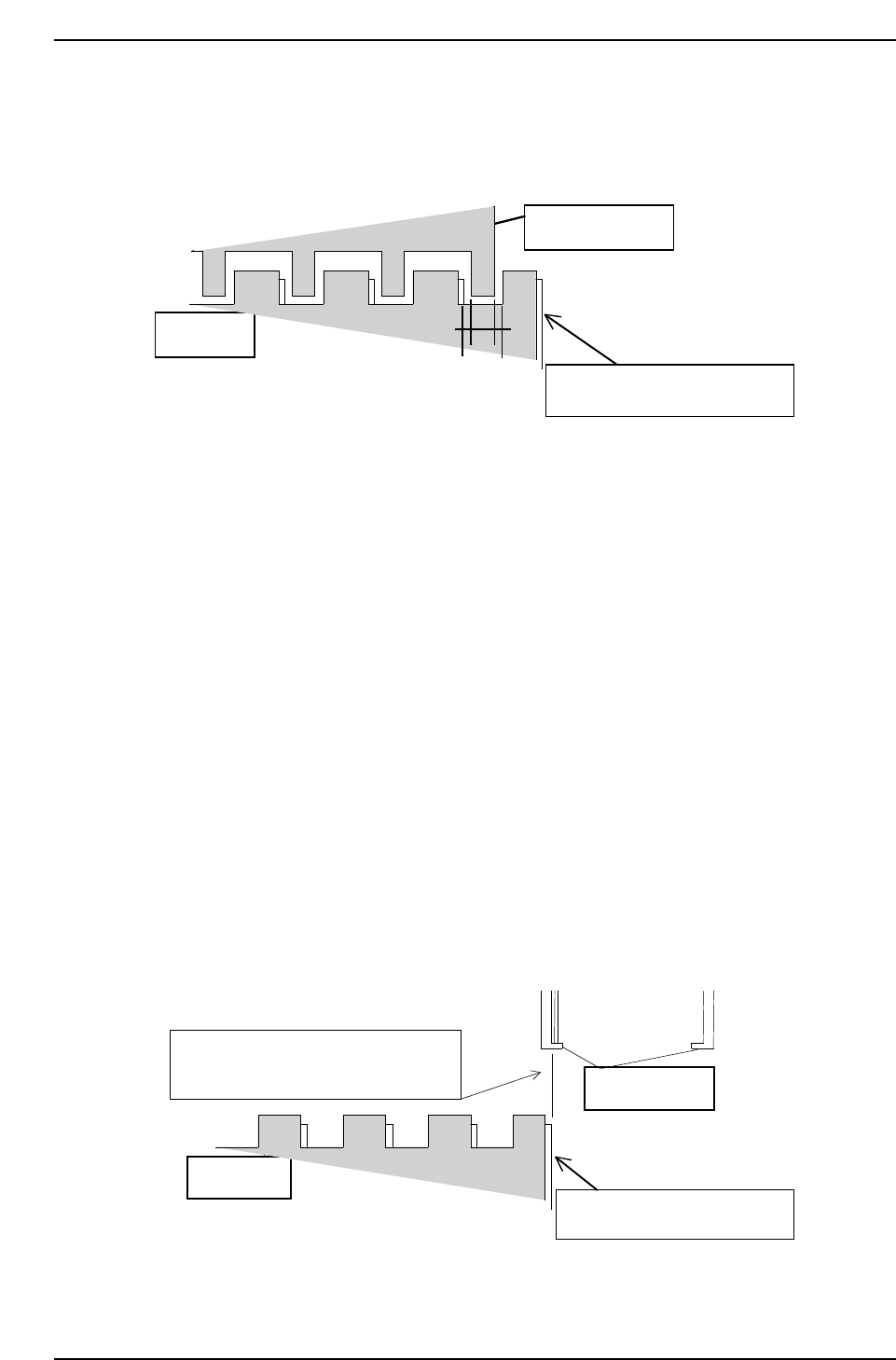
5. Move the PO-axis to the position where the second from the right jaw
aligns evenly within the right end cutout on the IN conveyor. Refer to
the illustration below.
6. Press [SET] → [PROPER] → [MIAIN UNIT] → [ETC] → [MANIPULATE]
→ [PLACE PO] → [SET] to record the value in Proper data.
2.2.2 PCB Pickup Position PO FWD
1. Press the EMERGENCY STOP button to shutdown the 200V.
2. Move the MX-axis to the pallet.
3. On the out-pallet loader, place an 8 inch pallet at position after shifting
10 mm.
4. Adjust the speed controller so that the manipulator descends slowly.
5. Press [SET] → [MANUAL] → [I/O] → [STANDARD I/O] → [OUTPUT]
and Y071 PCB UL DOWN.
6. Adjust the PO-axis so that the reference jaw of the manipulator is at the
center of the right end cut-out of the OUT conveyor.
Manipulator jaw
Out conveyor
QP132T2002
Chapter 2
2.2 Measuring Out Manipulator Proper Data and Adjustment
Edition 1.1 2-3 QP-132 Level 3 Tutorial
7. Press [SET] → [PROPER] → [MAIN UNIT] → [ETC.] → [MANIPULATE]
→ [AXIS CHG P0/(AXIS CHG MX9)] → [PK DIRECT PO] → [SET] to
record the value in Proper data.
2.2.3 PCB Pickup Position PO (Rotate-Loading)
1. Press the EMERGENCY STOP button to shutdown the 200V.
2. On the out-pallet loader, place the pallet at position after shifting 10 mm.
3. Press [SET] → [MANUAL] → [I/O] → [STANDARD I/O] → [OUTPUT]
and Y073 PCB UL HOOK CL to open the hook on the pallet.
4. Move the MX-axis to PCB_Pickup_Position.PO_FWD.
5. Press Y074 UL TURN to turn the manipulator.
6. Adjust the MX-axis so that the inner side of the reference jaw aligns with
the right edge of the 8-inch pallet.
7. Press [SET] → [PROPER] → [MAIN UNIT] → [ETC.] → [MANIPULATE]
→ [LD TURN/(PK PLACE P0)] → [SET] to record the value in Proper
data.
8-inch pallet
Inner side of reference jaw flushes with
the edge of the 8-inch pallet.
Manipulator jaw
Lower plate of the clamping jaw
QP1312T2004
QP132T2003
Manipulator jaw
Lower plate of the clamping jaw
8-inch pallet
Chapter 2
2.2 Measuring Out Manipulator Proper Data and Adjustment
Edition 1.1 2-4 QP-132 Level 3 Tutorial
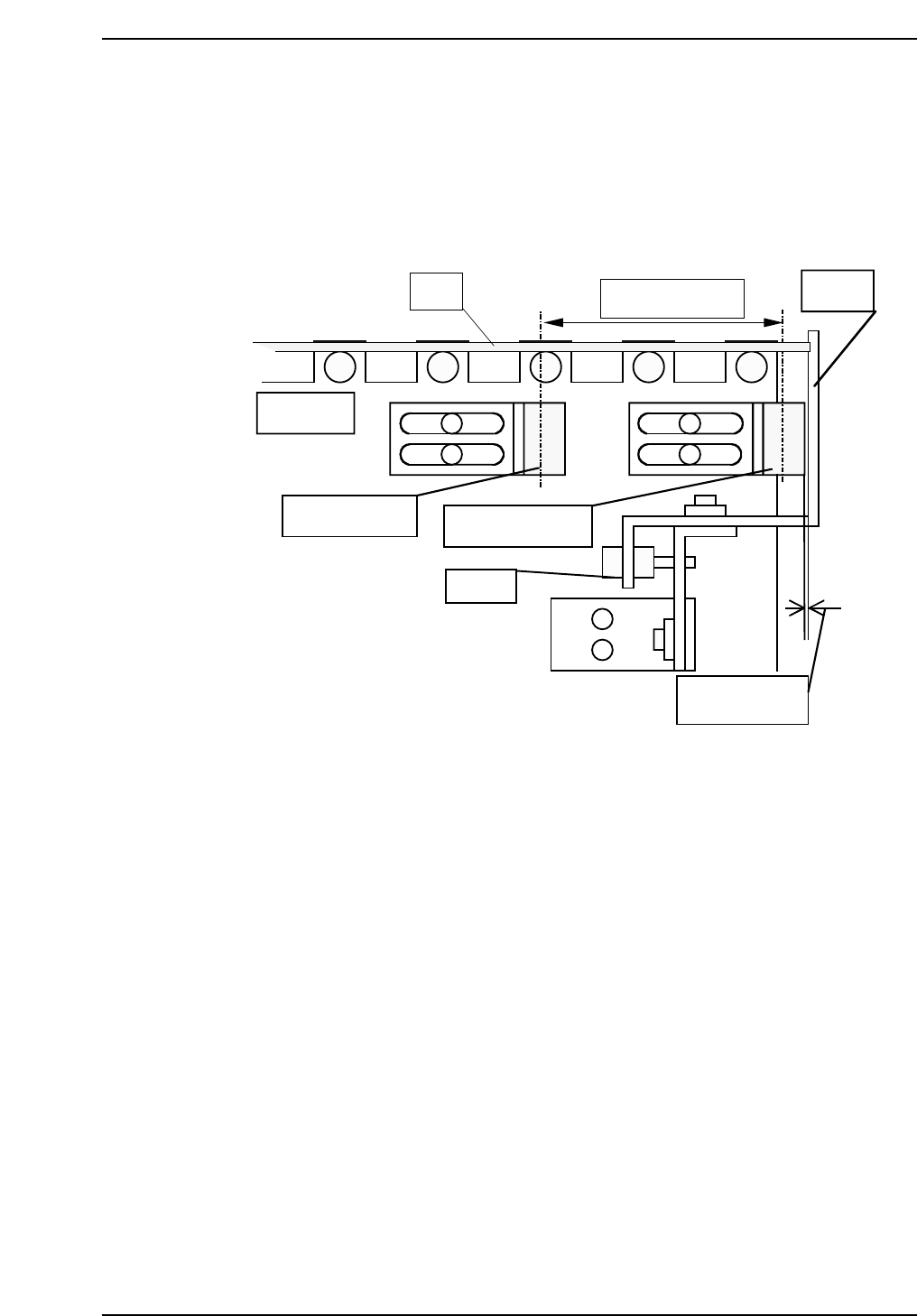
2.2.4 PCB Arrival Check and Reduction Sensors
1. Adjust the arrival check sensor to the position where the gap between
right surface of the sensor and stopper is 0.5 mm.
2. Adjust the reduction sensor to the position where the distance between
the reduction sensor and arrival check sensor is 60 mm.
QP132T2005
PCB
In conveyor
Approx. 60 mm
Stopper
Reduction sensor
Arrival check sensor
Adj. BT
Approx. 0.5 mm
Chapter 2
2.2 Measuring Out Manipulator Proper Data and Adjustment
Edition 1.1 2-5 QP-132 Level 3 Tutorial