QP132三级参考手册.pdf.pdf - 第51页
5. Move the SS-axis manually and check the clearance between the dogs and sensors. 6. Hold down the axis change key [3] and [Reset] key then press [Power] to boot the machine in mechanical check mode. 7. Press [INCH] → […
3.1 Replacing SS-Axis Motor
Required Jigs: SSO Calibration Jig
(CGPJ0010)
• Resolution : 0.0025 mm/pulses
• Pulses per rotation : 8000 pulses
• MY_reduce (deceleration distance) : 400 pulses
Zero set sensor position: 26 mm (10400 pulse) from minus side
mechanical stopper.
Zero set complete position: 15 mm (6000 pulse) from minus side
mechanical stopper.
Minus side overtravel sensor position: 5 mm (2000 pulse) from minus side
mechanical stopper.
Plus over side travel sensor position: 5 mm (2000 pulse) from plus side
mechanical stopper.
1. Remove the bracket fixing bolt and place it aside the machine. (The SS-
axis motor is positioned behind the solenoid valve bracket. The solenoid
valve is in the breaker box at the bottom left side of the machine.)
2. Replace the motor and make sure the SS-axis belt tension is temporarily
applied.
3. Use solenoid to move IN and OUT-pallet shifters to retract position.
4. Rotate the SS-axis pulley through a full-stroke to double check for any
interference and ensure that there are no obstacles around the SS-rail.
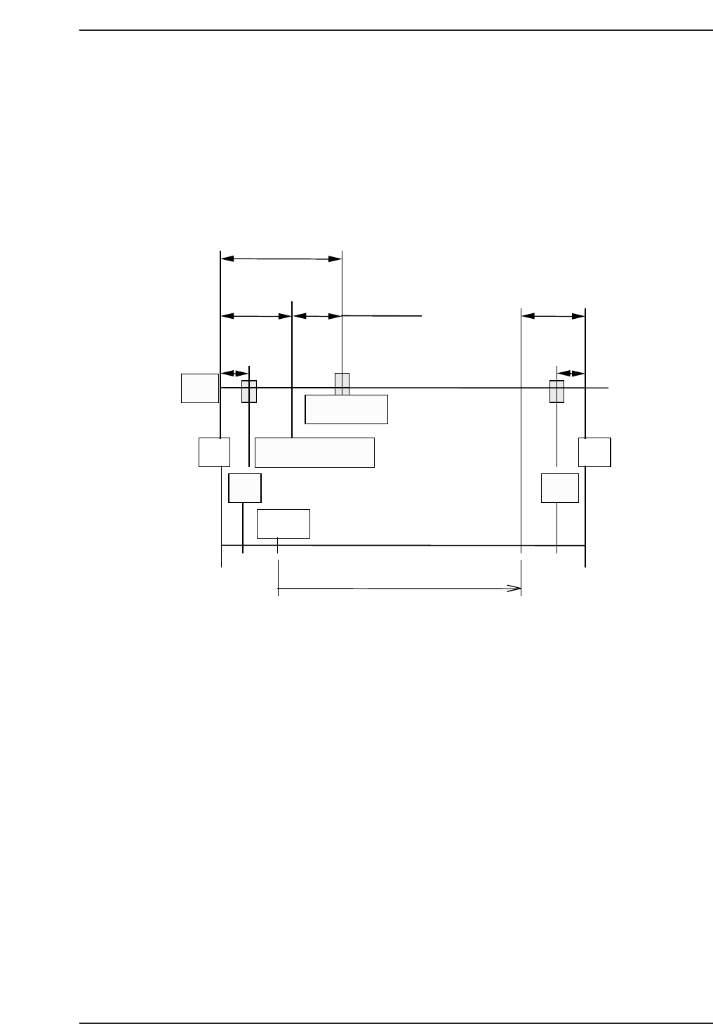
26 mm (10400 pulses)
15 mm (6000 pulses)
11 mm (4400 pulses)
Motor
5 mm
(2000 pulses)
5 mm
(2000 pulses)
-MS
Zero set complete pos.
Zero set sensor
SS Origin
-OT
11 mm
+MS
+OT
204 mm (8-inch indexing)
QP132T3001
Chapter 3 3.1 Replacing SS-Axis Motor
Edition 1.1 3-1 QP-132 Level 3 Tutorial

5. Move the SS-axis manually and check the clearance between the dogs
and sensors.
6. Hold down the axis change key [3] and [Reset] key then press [Power] to
boot the machine in mechanical check mode.
7. Press [INCH] → [Next data] or [Prev data] to select the SS-axis.
8. Press the EMERGENCY STOP button to shutdown the 200V.
9. Push the SS-axis against the minus (left) side mechanical stopper, record
the pulse count and move 2000 ± 200 pulse (5 mm) to plus (right) side.
10. Adjust the minus side overtravel dog so the sensor turns on at this
position.
11. Push the SS-axis against the plus (right) side mechanical stopper, record
the pulse count and move 2000 ± 200 pulse (5 mm) to minus (left) side.
12. Adjust the minus side overtravel dog so the sensor turns on at this
position.
13. Move the zero set dog to the right end of oval-shaped hole so the zero set
sensor turns ON away from the mechanical stopper.
14. Press [SERVO ON] → START to Servo ON and zero set.
15. After the completion of zero set, press the EMERGENCY STOP button to
turn OFF the 200V.
16. Remove the timing belt.
17. Push the SS-axis against the minus side mechanical stopper.
18. Rotate the motor to the counter value -6000 ± 200 pulse.
19. Reattach the belt. Belt Tension : f = 73 ± 10Hz.
20. Move the SS-axis to a servo count of 4400 ± 200 pluse and adjust the zero
set sensor to turn on at this position.
21. Press [SERVO ON] → START to Servo ON and zero set.
22. Press the EMERGENCY STOP button to shutdown the 200V and check
the position of the zero set sensor, plus and minus overtravel sensors.
Chapter 3 3.1 Replacing SS-Axis Motor
Edition 1.1 3-2 QP-132 Level 3 Tutorial
3.2 Measuring SS-Axis Proper Data and
Adjustment
3.2.1 Step Slide Origin SS
1. Complete the adjustment for the SS-axis zero set and overtravel sensors.
2. Move the SS-axis to the plus side slightly.
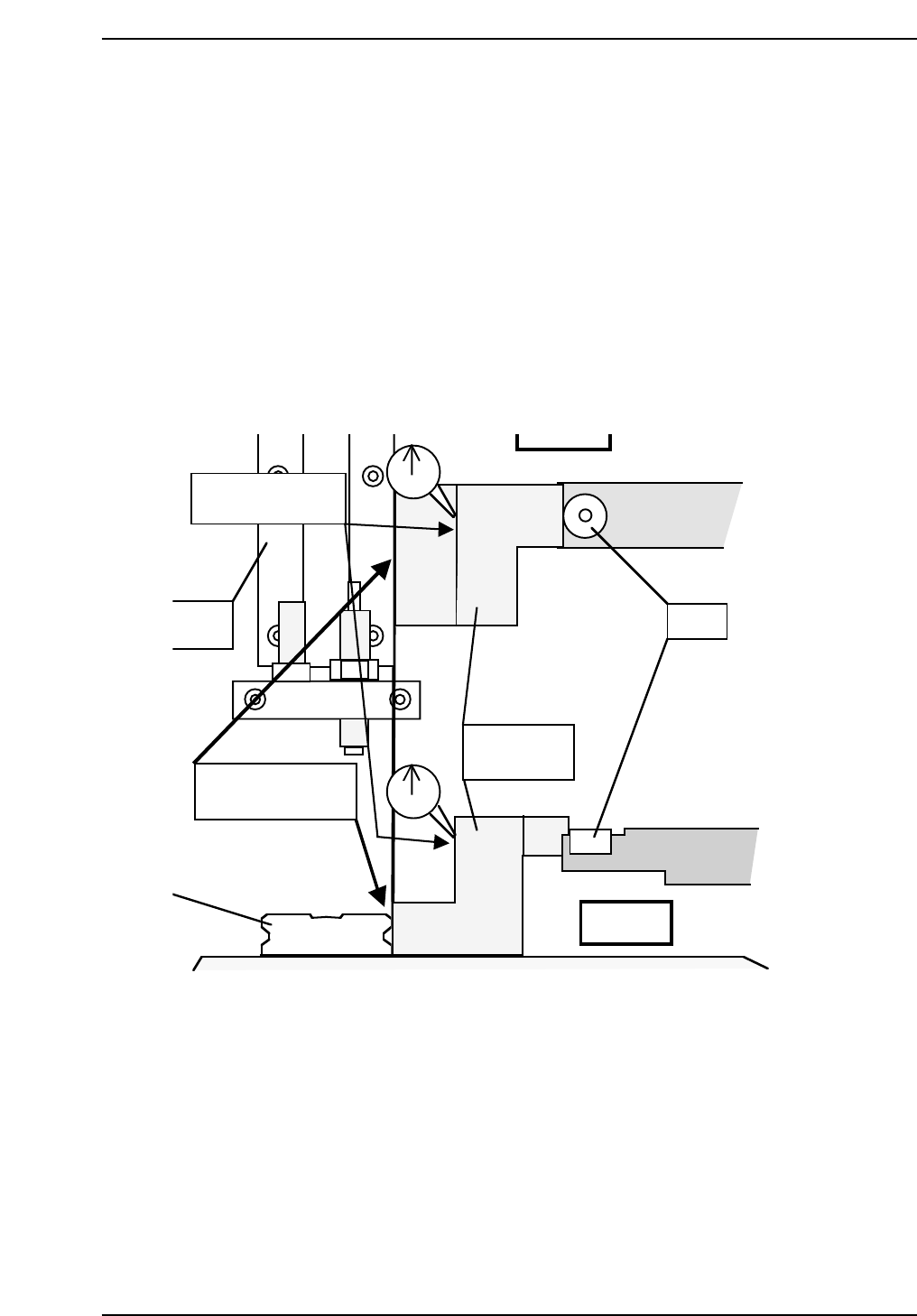
3. Set SS0 jig (CGPJ0010) to the LM guide as illustrated below.
4. Place a dial gauge as shown.
5. Move the SS-axis in the minus direction using the inching keys at low
speed.
QP132T3002
Set a dial gauge
to this surface of jig.
SS pin
N-shift
M guide
SS0
calibration jig
Side view
Put jig on the LM
guide to place.
Chapter 3 3.2 Measuring SS-Axis Proper Data and Adjustment
Edition 1.1 3-3 QP-132 Level 3 Tutorial