QP132三级参考手册.pdf.pdf - 第58页
PM Setting in Command 1. Boot the machine normally. 2. Press [SET] → [ MANUAL] → [ETC] → [ETC] → [MAINTENANCE] → enter ID CODE → [PMC SET]. 3. To boot all the modules, enter 255 to Working Module 3 and 4. Proper data is …

4.1 Setting Proper Data to Select PM
If the machine is booted in mechanical check mode, only the MX, MY, PO, and SS-
axes will be active. Therefore, to zero set the PM the machine needs to be booted
in normal mode.
However, it is dangerous if all axes move simultaniously during normal zero
setting. It is possible to select a PM to zero set by setting in the Proper data or by
commands at the machine.
PM Setting in Proper Data
Proper data 107: Working Module3 and 108: Working Module4
108: Working Module4: Setting of the placing head, 9 ~ 16
107: Working Module3: Setting of the placing head, 1 ~ 8
Example:
To select PM1
Set 108: Working Module4 to 1 + 2 = 3
To select PM11, 12, and 16
Set 107 Working Module3 to 4 + 8 + 128 = 140
To select all the modules
Set 108 Working Module4 to 1 + 2 + 4 + 8 + 16 + 32 + 64 + 128 = 255
Set 107 Working Module3 to 1 + 2 + 4 + 8 + 16 + 32 + 64 + 128 = 255
Then send Proper data to the machine.
Bit
7
6
5
4
3
2
1
0
Decimal
128
64
32
16
8
4
2
1
Placing Module
PM16
PM15
PM14
PM13
PM12
PM11
PM10
PM9
QP132T4002
Bit
7
6
5
4
3
2
1
0
Decimal
128
64
32
16
8
4
2
1
Placing Module
PM8
PM7
PM6
PM5
PM4
PM3
PM2
PM1
QP132T4001
Chapter 4 4.1 Setting Proper Data to Select PM
Edition 1.1 4-1 QP-132 Level 3 Tutorial

PM Setting in Command
1. Boot the machine normally.
2. Press [SET] → [ MANUAL] → [ETC] → [ETC] → [MAINTENANCE] →
enter ID CODE → [PMC SET].
3. To boot all the modules, enter 255 to Working Module 3 and 4. Proper
data is transmitted to the machine. Then the firmware is transmitted to
the PMC.
4. Turn OFF the machine power after transmission is completed, and re-
boot.
5. Press [SET] → [MANUAL] → [ETC] → [ETC] → [MAINTENANCE] →
enter ID CODE → [PMC SET] → PM number.
6. Turn OFF the machine power and reboot after every PMC is selected
using the commands.
7. Press [SET] → [MANUAL] → [ETC] → [PM] → [PM MAINTENANCE]
→ [PMC RBOOT] → [SET] → [MANUAL] → [ETC] → [PM] → [PM
MAINTENANCE] → [ZERO SET] → START.
Note: When power is supplied to the machine, the vision processing unit will boot. Only the
selected PMC will be checked and registered to the VP board at this time.
Only PM1 will be registered if only PM1 is set during machine re-boot. Therefore, it is
not possible to set the other PMs using the machine commands after the machine is re-
booted.
Chapter 4 4.1 Setting Proper Data to Select PM
Edition 1.1 4-2 QP-132 Level 3 Tutorial
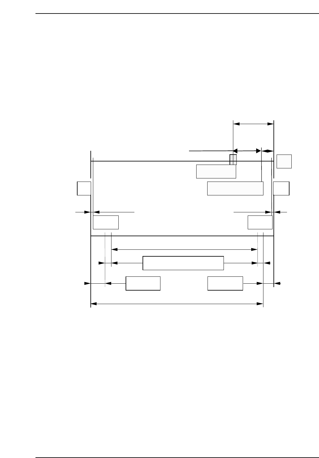
4.2 Replacing X-Axis Motor
This applies to machine X No. 4 to 12.
The mechanical stroke in the X-direction is different for No’s. 4 ~ 12 and 13 and
later.
Max. stroke (Between mechanical stoppers) : 137 mm
Max placing range : 127.5 mm
Resolution : 0.010 mm/pulse
Pulses per rotation : 2000 pulses
X_reduce (deceleration distance) : 500 pulses
Zero set sensor position: 15 mm (1500 pulses) from the minus mechanical
stopper.
Zero set complete position: 5 mm (500 pulses) from the minus mechanical
stopper.
QP132T4003
-MS
0.5 mm 0.5 mm
Soft limit Soft limit
10 mm
(1000 pulses)
20 mm (-2000 pulses)
+MS
Motor
Zero set sensor
Zero set complete pos.
5 mm
(500 pulses)
3.011 mm
6 mm 6 mm
137 mm (Max. stroke)
Nozzle offset Nozzle offset
Mark reading + VP compensation
127.5 mm (Max. placement range)
2.489 mm
Chapter 4 4.2 Replacing X-Axis Motor
Edition 1.1 4-3 QP-132 Level 3 Tutorial