QP132三级参考手册.pdf.pdf - 第6页
Body The information needed to understand the workings of the machine and how to perform operation is explained using text and illustrations. Page number A two digit hyphenated number appears in the footer on each page. …
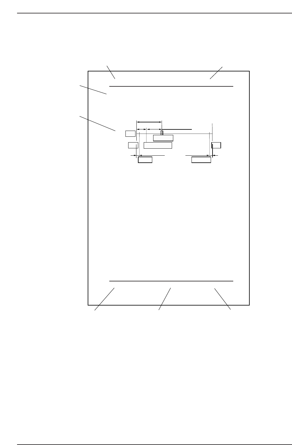
Page Layout
Each page indicates the chapter number, section title and number, body, manual name,
page number, and the edition number.
Chapter number
The chapter number to which each section belongs is shown on the header on each page.
The manual is made up of twelve chapters as detailed earlier in this section.
Section number and title
The title of each chapter is shown in the header on each page. Each part may contain one
or more sections.
Section title
Each chapter may be divided into several sections. The section number is composed of
the number of the chapter to which the section belongs, followed by a sequential number
for each section.
Chapter number
Section number and title
Section title
Body
Edition number
Page number
Manual name
QP132T0001
1.1 Replacing MX Axis Motor
¥ Resolution : 0.005mm 0.0025/pulse
¥ Pulse per rotation : 4000 8000 pulse
¥ MX_reduce (deceleration distance) : 500 1000 pulse
Zero set sensor position: 22.5 mm (44008800 pulse) from minus side
mechanical stopper.
Zero set complete position: 10 mm (20004000 pulse) from minus side
mechanical stopper.
Note: Machine ROM version 1.52 or above, use figures in the square.
1. Replace the motor and ensure that the coupling is tightened.
2. Hold down the axis change key [3] and [Reset] key then press [Power
On] to boot the machine in mechanical check mode.
3. Press E-stop to shutdown 200V.
4. Push the MX-robot against the minus side mechanical stopper.
5. Move the zero set dog to the left end of oval-shaped hole so the zero set
sensor turns ON away from the mechanical stopper.
6. Move the MX-robot to the center of the stroke.
7. Press [INCH] → [Next data] or [prev data] to select the MX axis.
8. Press [SERVO ON] → [Start] to Servo ON and zero set.
9. After completion of sero set, press the E- Stop button turn OFF the 200V.
10. Loosen the coupling and push e the MX-robot against the minus side
mechanical stopper.
11. Rotate the motor to the value -2000 -4000 +/- 200 400 pulse.
12. Tighten the coupling. Coupling Torque: 3.33 Nm (0.34 kgf/m)
13. Push the MX-robot against the minus side mechanical stopper and check
the servo counter value. -2000 -4000 +/- 200 400 pulse.
14. Move the robot to the value 2400 4800 +/- 200 400 pulse.
15. Adjust the dog position so the zero set sensor turns ON at this position.
16. Press [SERVO ON] → [Start] to Servo ON and zero set again.
17. After completion of sero set, press the E- Stop button turn OFF the 200V.
18.
Move the MX-robot to the position where zero set sensor turns on and
make sure the servo counter value is 2400 4800 +/- 200 400 pulse.
22.5 mm (4400 [8800] pulse)
12.5 mm (2400 [4800] pulse)
3.5 mm (700 [1400] pulse) 1 mm (200 [400] pulse)
+MSZero-set complete pos.
Zero-set sensor
Motor
-MS
Soft limit Soft limit
QP13221001
10 mm (2000 [4000] pulse)
Chapter 1 1.1 Replacing MX Axis Motor
Edition 1.0 1-1 QP-132 Level 3 Tutorial
About This Manual
Edition 1.1 ii QP-132 Level 3 Tutorial

Body
The information needed to understand the workings of the machine and how to perform
operation is explained using text and illustrations.
Page number
A two digit hyphenated number appears in the footer on each page. The first digit of
each page number indicates the chapter number and the second digit is the sequential
page number within that chapter. Page 1-2, for example, indicates that this is the second
page in the first chapter.
Manual name
The name of the manual that appears on the cover is also shown in the footer on each
page.
Edition number
The edition number is updated each time the manual is revised, with the number
reflecting the scale of changes that were made.
Minor revision: Minor changes are reflected in the part of the edition number after
the decimal point, for example, a change from edition 1.0 to 1.1. This
change is made on the revised pages only, and these pages can be
downloaded as required from Fuji's website.
Major revision: If major changes are made, the edition number is increased by one,
for example, a change from edition 1.0 to 2.0. This change is made on
all pages, including the cover.
Notation Conventions Used in this Manual
The notation conventions employed in this manual are described below.
[Production] command The names of the command buttons are enclosed in brackets,
and use the verb “press”.
START button Buttons on the machine are written exactly as they appear,
and use the verb “press”.
“Production” command section The names of commands that have been grouped
together are enclosed in quotation marks.
[TAB] key Keys on the keyboard appear in brackets.
About This Manual
Edition 1.1 iii QP-132 Level 3 Tutorial

Terminology Notice
“Production Program” In this manual the term “production program” is
used to refer to the operating instructions used by
the machine in the production of a board.
In FujiCam, Fuji’s latest host system, this data is
referred to as the “recipe”.
Despite the differences in name, the terms carry the
same meaning, and references to “production
program” may therefore be thought of as “recipe” by
FujiCam users.
“Board”, “Block” In this manual the term “board” is used to refer to
the printed circuit on which parts are placed, and the
term “block” is used for multiple identical circuits
that may exist within a board and which are split
into individual units when production is complete.
In FujiCam, Fuji’s latest host system, these terms are
referred to as “panel” and “board” respectively.
Despite the differences in name, the terms used in
this manual carry the same meaning as the
corresponding FujiCam terminology and can
therefore be freely interchanged by FujiCam users.
Purpose of This Technical Training
- Provide knowledge and practical training for recovering the machine by
troubleshooting including measurement of Proper data.
- Carry out practical training for changing the sliding parts (such as IP-III
spline shaft)
- Give practical exerciseon how to locate troubles and recover the machine
when the machine cannot be recovered by simple replacement of a camera,
a servo amplifier or a motor.
Person Qualified for This Training
Manufacturing line manager, factory manager or a person in equivalent position who
has already completed the Level 2 training.
About This Manual
Edition 1.1 iv QP-132 Level 3 Tutorial