QP132三级参考手册.pdf.pdf - 第66页
Notes: Chapter 4 4.4 Replacing Q-Axis Zero Motor Edition 1.1 4-10 QP-132 Level 3 T utorial
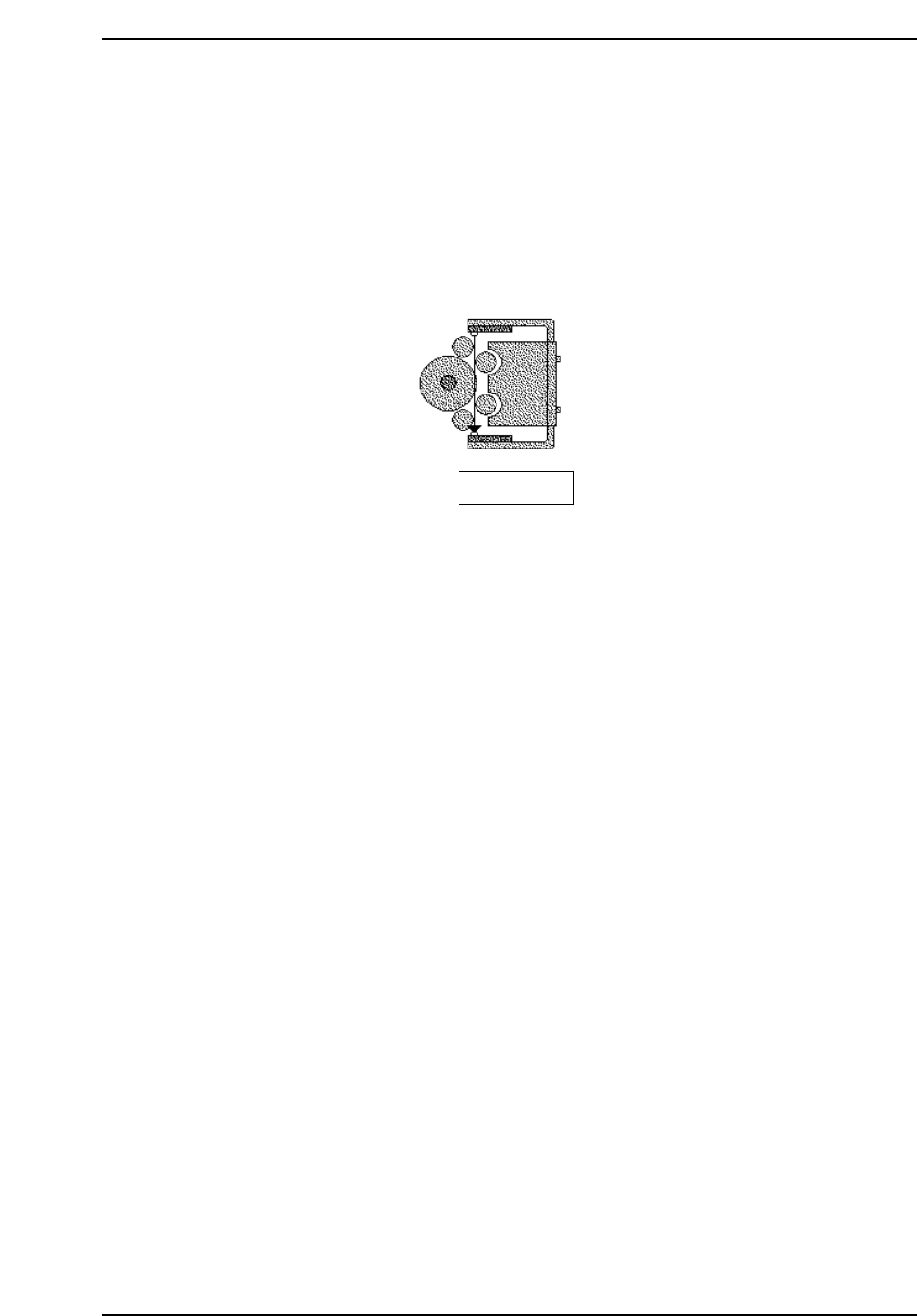
4.4 Replacing Q-Axis Zero Motor
1. There is no zero set sensor for the Q-axis.
2. Timing Belt Tension f = 295 Hz ± 10 Hz
Note: After the Q-motor is attached, move the placing head manually and check for any
interference with motors, cables, etc.
Bottom view
QP132T4006
Chapter 4 4.4 Replacing Q-Axis Zero Motor
Edition 1.1 4-9 QP-132 Level 3 Tutorial

Notes:
Chapter 4 4.4 Replacing Q-Axis Zero Motor
Edition 1.1 4-10 QP-132 Level 3 Tutorial
4.5 Measuring PM Proper Data and
Adjustment
Required Jigs: Dial Indicator jig (Z9214CGQJ9100)
Z0 Jig (Z9214CGQJ0050)
Nozzle Jig (Z9214ACGP8002)
Nozzle Jig (ACGPJ9021)
X0, Y0 Calibration Jig (ACGPJ9030)
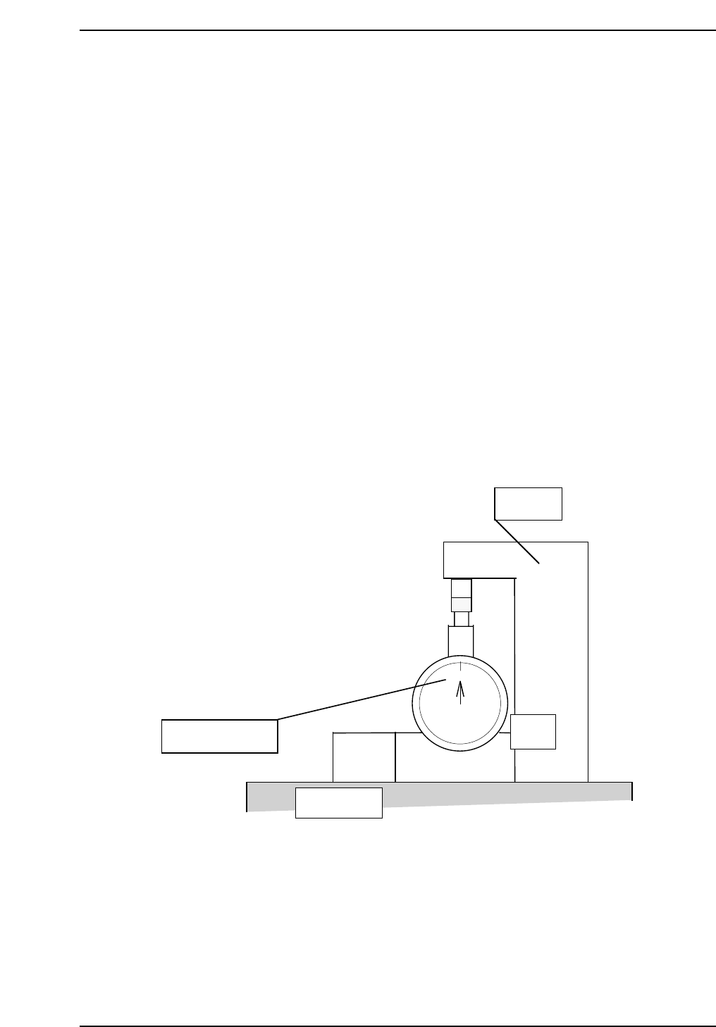
4.5.1 Placement Height
1. Turn OFF the 200V.
2. Place a dial indicator jig (Z9214CGQJ9100) to the SS-rail.
3. Place a Z0 jig (Z9214CGQJ0050) to the SS.
4. Set the scale to zero.
5. Move the dial gauge jig to the SS-rail within the placement area.
6. Install a nozzle jig (Z9214ACGP8002) to the holder.
7. Press [SET] → [MANUAL] → [I/O] → [STANDARD I/O] → [OUTPUT]
and PY04 NZL A VACUUM to turn on the vacuum.
0
QP132T4007
Set a scale to zero.
SS-rail top
Ref. block
Z0 jig
Chapter 4 4.5 Measuring PM Proper Data and Adjustment
Edition 1.1 4-11 QP-132 Level 3 Tutorial