QP132三级参考手册.pdf.pdf - 第67页
4.5 Measuring PM Proper Data and Adjustment Required Jigs: Dial Indicator jig (Z9214CGQJ9100) Z0 Jig (Z9214CGQJ0050) Nozzle Jig (Z9214ACGP8002) Nozzle Jig (ACGPJ9021) X0, Y0 Calibration Jig (ACGPJ9030) 4.5.1 Placement He…

Notes:
Chapter 4 4.4 Replacing Q-Axis Zero Motor
Edition 1.1 4-10 QP-132 Level 3 Tutorial
4.5 Measuring PM Proper Data and
Adjustment
Required Jigs: Dial Indicator jig (Z9214CGQJ9100)
Z0 Jig (Z9214CGQJ0050)
Nozzle Jig (Z9214ACGP8002)
Nozzle Jig (ACGPJ9021)
X0, Y0 Calibration Jig (ACGPJ9030)
4.5.1 Placement Height
1. Turn OFF the 200V.
2. Place a dial indicator jig (Z9214CGQJ9100) to the SS-rail.
3. Place a Z0 jig (Z9214CGQJ0050) to the SS.
4. Set the scale to zero.
5. Move the dial gauge jig to the SS-rail within the placement area.
6. Install a nozzle jig (Z9214ACGP8002) to the holder.
7. Press [SET] → [MANUAL] → [I/O] → [STANDARD I/O] → [OUTPUT]
and PY04 NZL A VACUUM to turn on the vacuum.
0
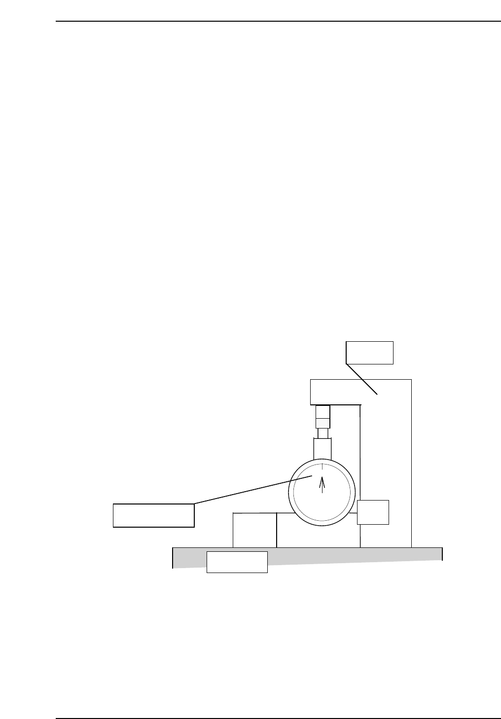
QP132T4007
Set a scale to zero.
SS-rail top
Ref. block
Z0 jig
Chapter 4 4.5 Measuring PM Proper Data and Adjustment
Edition 1.1 4-11 QP-132 Level 3 Tutorial
8. PY04 NZL A DOWN to lower the holder A.
9. Move the head manually. Place the nozzle jig softly on to the dial
indicator.
10. Adjust the head height. Make sure that the head is not tilting.
11. Check holders B, C and D heights using a dial indicator. Obtain the
average height for all four. Finalize the head height. The deviation of
the four heights shall be less than ± 0.06 mm.
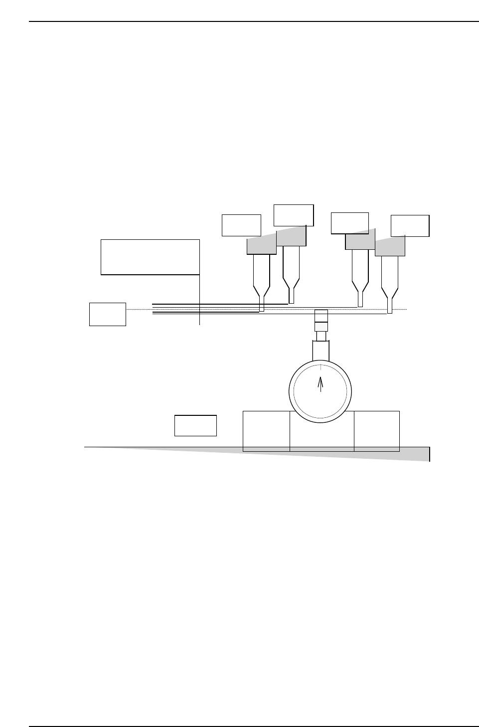
0
Average
height
SS-rail top
Obtain the average height
and adjust the height by a
dial indicator to finalize.
Holder, D
Holder, C
Holder, B
Holder, A
QP132T4008
Chapter 4 4.5 Measuring PM Proper Data and Adjustment
Edition 1.1 4-12 QP-132 Level 3 Tutorial