QP132三级参考手册.pdf.pdf - 第74页
5.1 Replacing Mark Camera Required Jigs: Mark Camera Adjusting Jig (ACGPJ9030) 1. Set the gain dip switch to “M”. The switch is located behind the camera. 2. Set the clearance between the dispersion sheet of the light un…

Chapter 5
Mark Camera

5.1 Replacing Mark Camera
Required Jigs: Mark Camera Adjusting Jig
(ACGPJ9030)
1. Set the gain dip switch to “M”. The switch is located behind the camera.
2. Set the clearance between the dispersion sheet of the light unit and the
tip of the half mirror to 1 mm. After adjustment, apply loctite to the set
screws on the half mirror.
3. Input zero to Proper data.
108 Working Module4
107 Working Module3
4. Send Proper data to the machine and reboot.
5. Press [SET] → [MANUAL] → [ETC] → [PM] → [PM MAINTENANCE]
→ [ZERO SET] → START to zero set.
6. After the completion of zero set, press [SET] → [SERVO] → [SS MOVE]
or set the SS-axis to the SS0 position using the inching keys.
7. Set a mark camera adjusting jig (ACGPJ9030) to the pallet.
8. Place the pallet to the SS-rail at mark read station (SS0).
9. Press [SET] → [MANUAL] → [I/O] → [STANDARD I/O] → [OUTPUT]
and I/O Out Y04D SS PLT CLP1 to clamp.
10. Press [SET] → [PROPER] → [MAIN UNIT] → [MARK CAMERA] →
[RSLTION/CNTR] to display the image.
Chapter 5 5.1 Replacing Mark Camera
Edition 1.1 5-1 QP-132 Level 3 Tutorial
11. Check the displayed image and adjust the gain volume behind the
camera.
12. Adjust the focus using the Focus adj. bolt on top of the camera bracket.
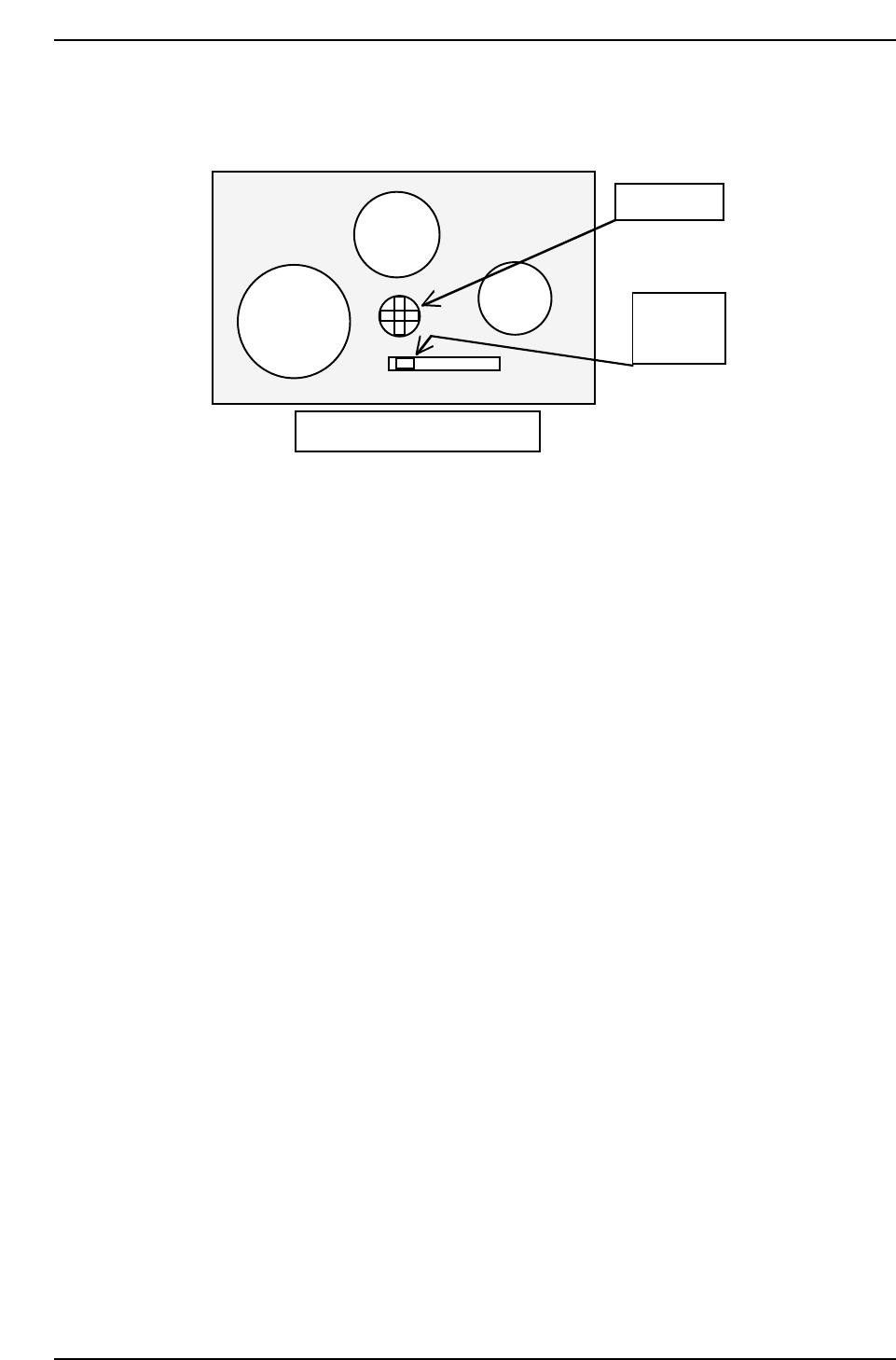
Rear side of the mark camera
Set switch
to M
Gain volume
QP132T5001
M F A GAIN
Chapter 5 5.1 Replacing Mark Camera
Edition 1.1 5-2 QP-132 Level 3 Tutorial