QP132三级参考手册.pdf.pdf - 第82页
11. Raise the camera 0.5 mm from the focused position. Note: Special lenses are used by the QP132 Parts cameras. Therefore, the focus distance is about 6.0 mm. Do not lower the camera to focus. Move the unit upward from …

6.1 Replacing Parts Camera
Required Jigs: Resolution Jig
(ACGPJ9060)
1. Check if the lens is locked at the torque value indicated.
(Torque --- 4.41 Nm = 45 Kgcm)
2. Replace the camera. Attach the UV lamp and regulator, and connect the
wiring.
3. Enter 255 to the Proper data, [107 Working Module3 108 Working
Module4] for each.
4. Boot the machine, transmit the Proper data and zero set.
5. Or press [SET] → [MANUAL] → [ETC] → [ETC] → [MAINTENANCE]
→ enter ID No. → [PMC setting] and select either ON or OFF. After the
setting, re-boot the machine.
6. Press [SET] → [PROPER] → ID No. → [PM] → select the module to focus
→ [Part Camera] → [Cross line display] to display the image.
7. Attach the nozzle to the lowest positioned nozzle holder.
8. Turn OFF the 200V.
9. Move the placing head manually and display the nozzle on the monitor.
10. Focus the Parts camera. The camera needs to be placed at the lowest
position first. Then move the camera up to the focused position.
Chapter 6 6.1 Replacing Parts Camera
Edition 1.1 6-1 QP-132 Level 3 Tutorial
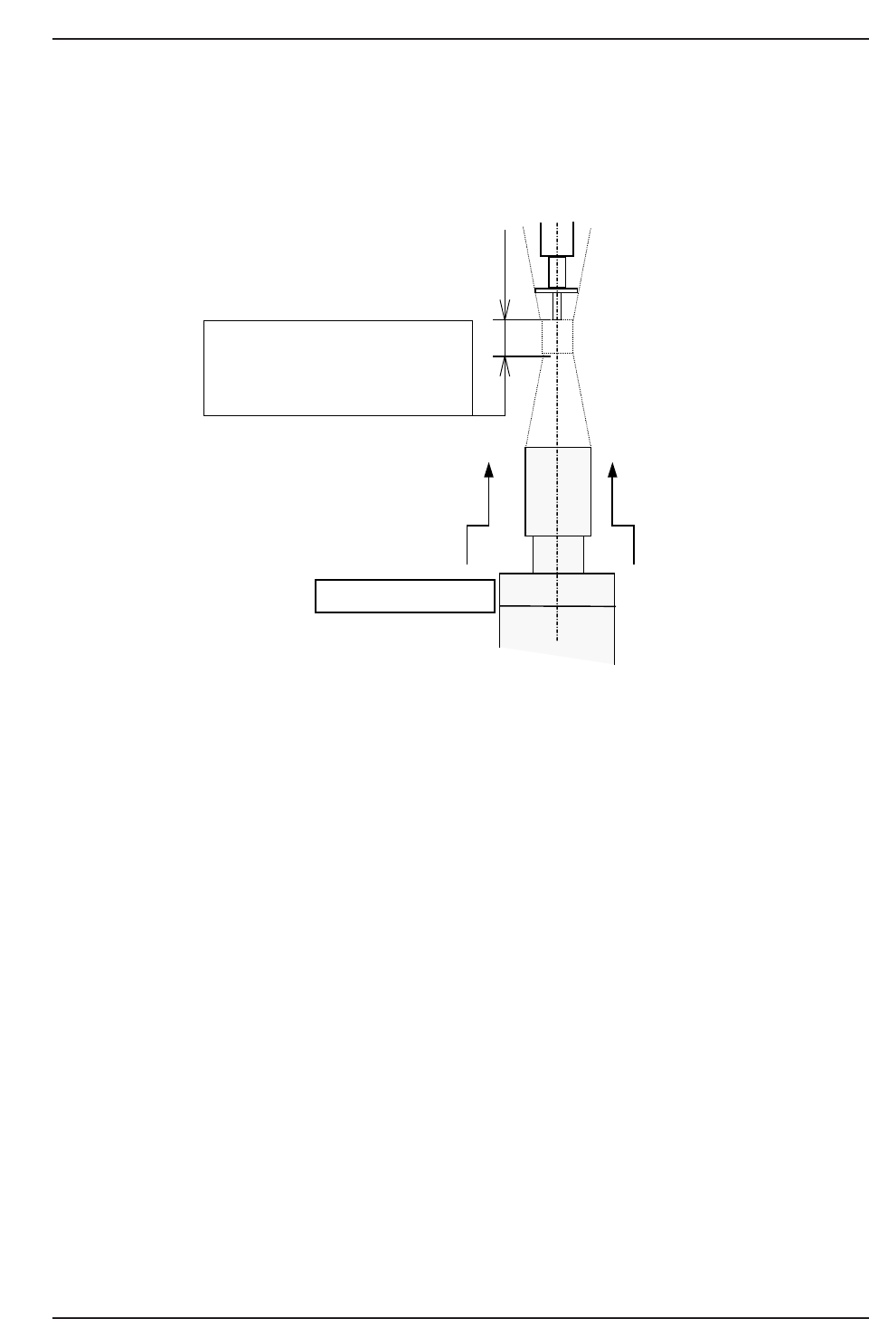
11. Raise the camera 0.5 mm from the focused position.
Note: Special lenses are used by the QP132 Parts cameras. Therefore, the focus distance is
about 6.0 mm. Do not lower the camera to focus. Move the unit upward from the
bottom.
QP132T6001
The focus area of parts camera has
approx. 6.0 mm.
Then adjust the nozzle tip until it is
just focused.
Focus from the bottom.
Chapter 6 6.1 Replacing Parts Camera
Edition 1.1 6-2 QP-132 Level 3 Tutorial
6.2 Measuring Parts Camera Proper Data and
Adjustment
6.2.1 Delta and Parts Camera Pixel
1. Attach a resolution jig (ACGPJ9060) to holder A.
2. Set a dial indicator on the side of jig.
3. Move the X-axis using the inching keys. Rotate Q and the placing head
and position the side of jig to parallel to the X-axis.
Tolerance : 0.01 mm
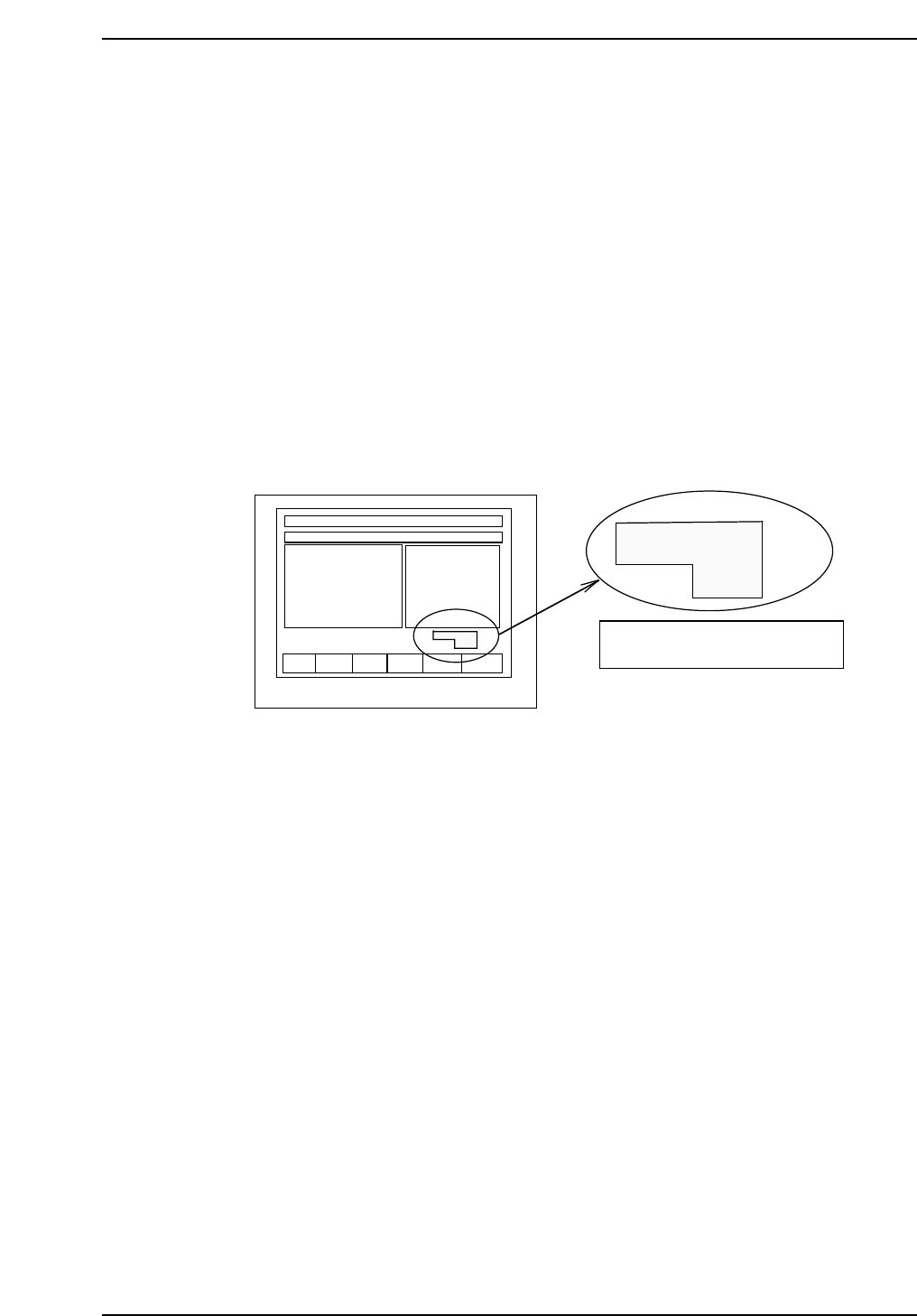
Note: When using the inching keys, check the desired PM. Check the jog display at the bottom
right of the monitor.
4. Press [SET] → [PROPER] → ID No. → [PM] → select the module to be
focused → [FINISH] → [Part Camera] → [Crosshair display] to display
the image.
5. Move the resolution jig to the center of the camera using the inching
keys.
6. Press [SET] → [PROPER] → Enter ID No. → [PM] → select the module →
[Part Camera] → [Resolution] → START.
Delta X: ± 50.0 um
Delta Y: ± 50.0 um
Delta Q: less than ± 0.050 deg.
X: 24.500 ± 0.5 um
Y: 24.500 ± 0.5 um
7. Adjust the camera height and angle.
8. Re-tighten and check the resolution several times.
F1 F2 F3 F4 F5 F6
jog X Y θ
PM01
Check the axis to be jogged and
PM no. in this display.
QP132T6002
Chapter 6
6.2 Measuring Parts Camera Proper Data and Adjustment
Edition 1.1 6-3 QP-132 Level 3 Tutorial