QP132三级参考手册.pdf.pdf - 第85页
Note: It is possible to attach 8.0 mm backlight disks to holders A, B, C and D when using small nozzles. As for larger disks, (17.0 backlight disks), they should be attached to holders A and D and are referred to as nozz…
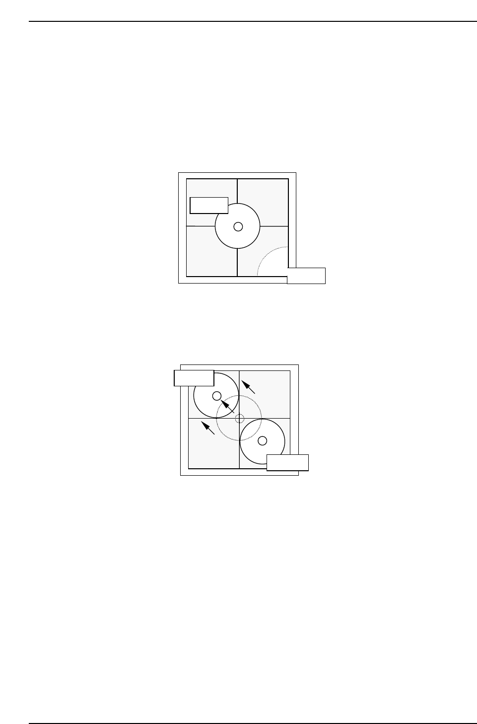
6.2.2 Camera Center
1. Press [SET] → [PROPER] → ID No. → [PM] → select the module →
[FINISH] → [Part Camera] → [Crosshair display] to display an image.
2. Attach a 1.3 diameter nozzle to holder A, B, C and D.
3. Use the inching keys to move reference nozzle A to the camera center.
4. Press [Part Camera] → [Camera Center] → Select the nozzle AB →
[EXECUTE]. The nozzle will move between nozzle A and B to auto-
calibrate.
5. Use the inching keys to move reference nozzle D to the camera center.
6. Press [Part Camera] → [Camera Center] → Select the nozzle CD →
[EXECUTE]. The nozzle will move between nozzle C and D to auto-
calibrate.
QP132T6004
Nozzle A
Nozzle B
QP132T6003
Nozzle A
Nozzle B
Chapter 6
6.2 Measuring Parts Camera Proper Data and Adjustment
Edition 1.1 6-4 QP-132 Level 3 Tutorial
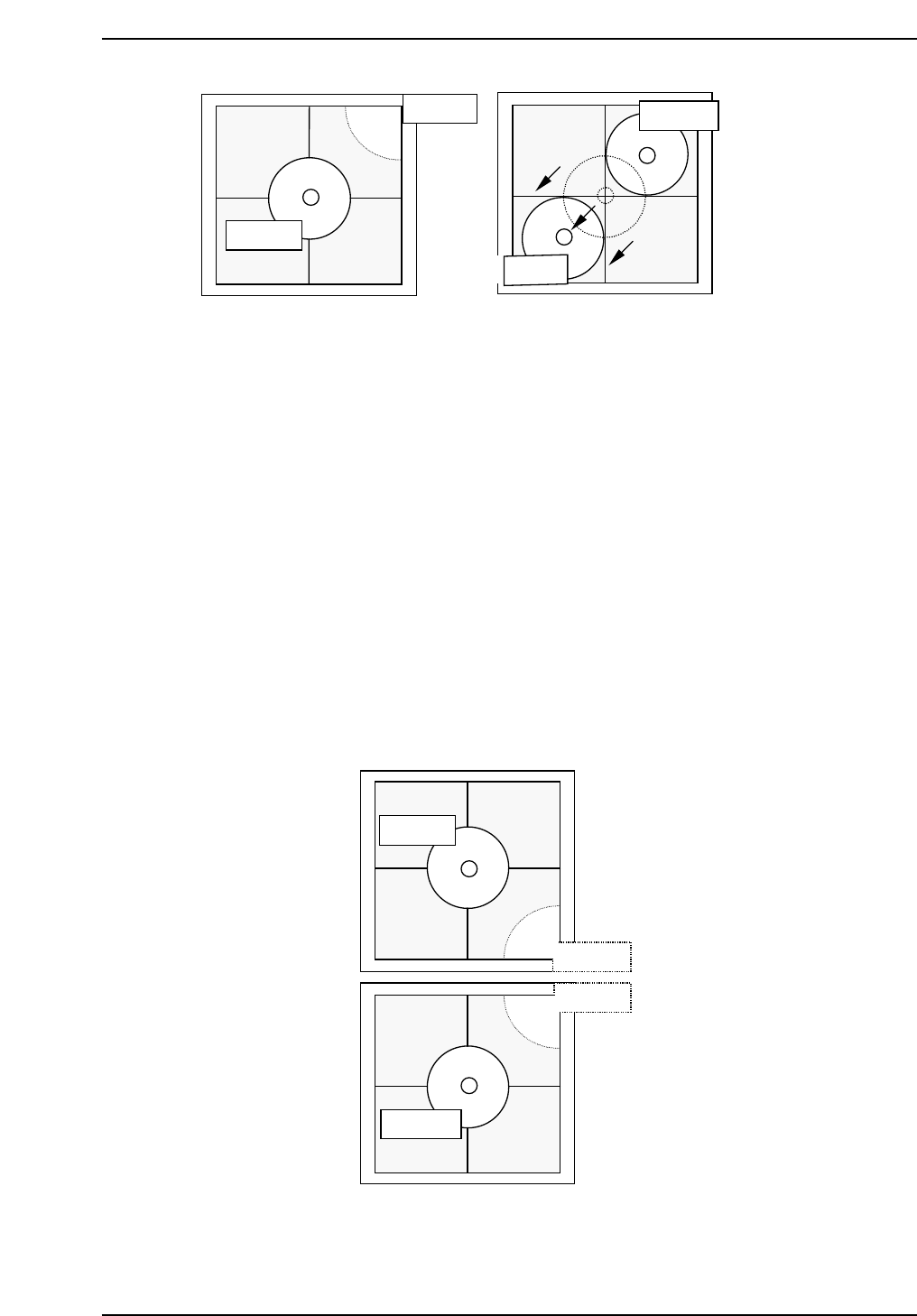
Note: It is possible to attach 8.0 mm backlight disks to holders A, B, C and D when using small
nozzles. As for larger disks, (17.0 backlight disks), they should be attached to holders A
and D and are referred to as nozzles E and F. Therefore, nozzles A and E, D and F use
the same holders. Separate Proper data measurement if necessary.
7. Press [SET] → [PROPER] → ID No. → [PM] → select the module →
[FINISH] → [Part Camera] → [Crosshair display] to display a real image
of the nozzle on the monitor.
8. Attach a 1.3 diameter nozzle to holder E (A) and F (D).
9. Use the inching keys to move reference nozzle E to the camera center
10. Press [Part Camera] → [Camera Center] → Select the nozzle E → [SET].
11. Press [Part Camera] → [Camera Center] → Select the nozzle F → [SET].
QP132T6006
Nozzle E
Nozzle B
Nozzle C
Nozzle F
QP132T6005
Nozzle C
Nozzle C
Nozzle D
Nozzle D
Chapter 6
6.2 Measuring Parts Camera Proper Data and Adjustment
Edition 1.1 6-5 QP-132 Level 3 Tutorial
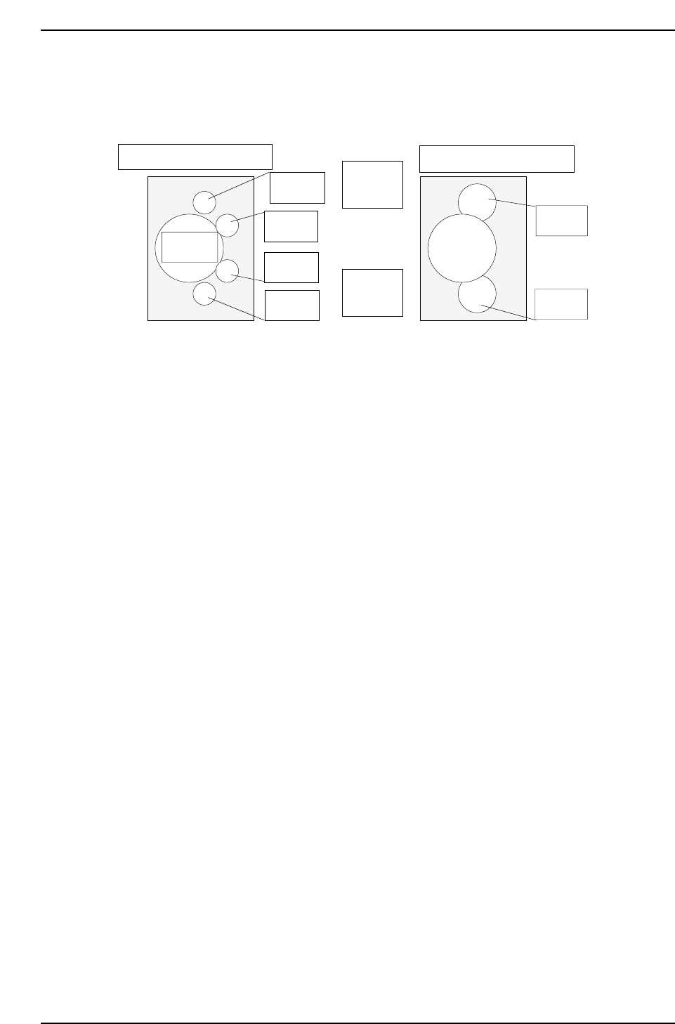
6.2.3 Nozzle_A Holder Center
Note: This measures nozzle center and replaces the Proper data.
1. Attach a 1.3 diameter nozzle to holder A, B, C and D.
2. Press [PROGRAM] → [CHANGE] → Select program PORP_8 to the
foreground.
3. Press [AUTO] to transmit the program to the PMC .
4. Press [SET] → [PROPER] → ID No. → [PM] → select the module →
[FINISH] → [Part Camera] → [CALIB CNTR] → [In turn meas] →
[EXECUTE] → Enter a starting PM No. and final PM No. → START.
5. Attach a 1.3 diameter nozzle to holder E (A) and F (D).
6. Press [PROGRAM] → [CHANGE] → Select program to PORP_17 to the
foreground.
7. Press [AUTO] to transmit the program to the PMC.
8. Press [SET] → [PROPER] → ID No. → [PM] → Select the module. →
[FINISH] → [Part Camera] → [CALIB CNTR] → [In turn meas] →
[EXECUTE] → Enter a starting PM No. and final PM No. → START.
Q gear
↑
QP132T6007
View from top of X-axis head
Nozzle A
Nozzle B
Nozzle C
Nozzle D
Nozzle E
Nozzle F
(M/C rear)
↓
(M/C front)
View from top of X-axis head
Chapter 6
6.2 Measuring Parts Camera Proper Data and Adjustment
Edition 1.1 6-6 QP-132 Level 3 Tutorial