QP132三级参考手册.pdf.pdf - 第86页
6.2.3 Nozzle_A Holder Center Note: This measures nozzle center and replaces the Proper data. 1. Attach a 1.3 diameter nozzle to holder A, B, C and D. 2 . Press [PROGRAM] → [CHANGE] → Select program PORP_8 to the foregrou…
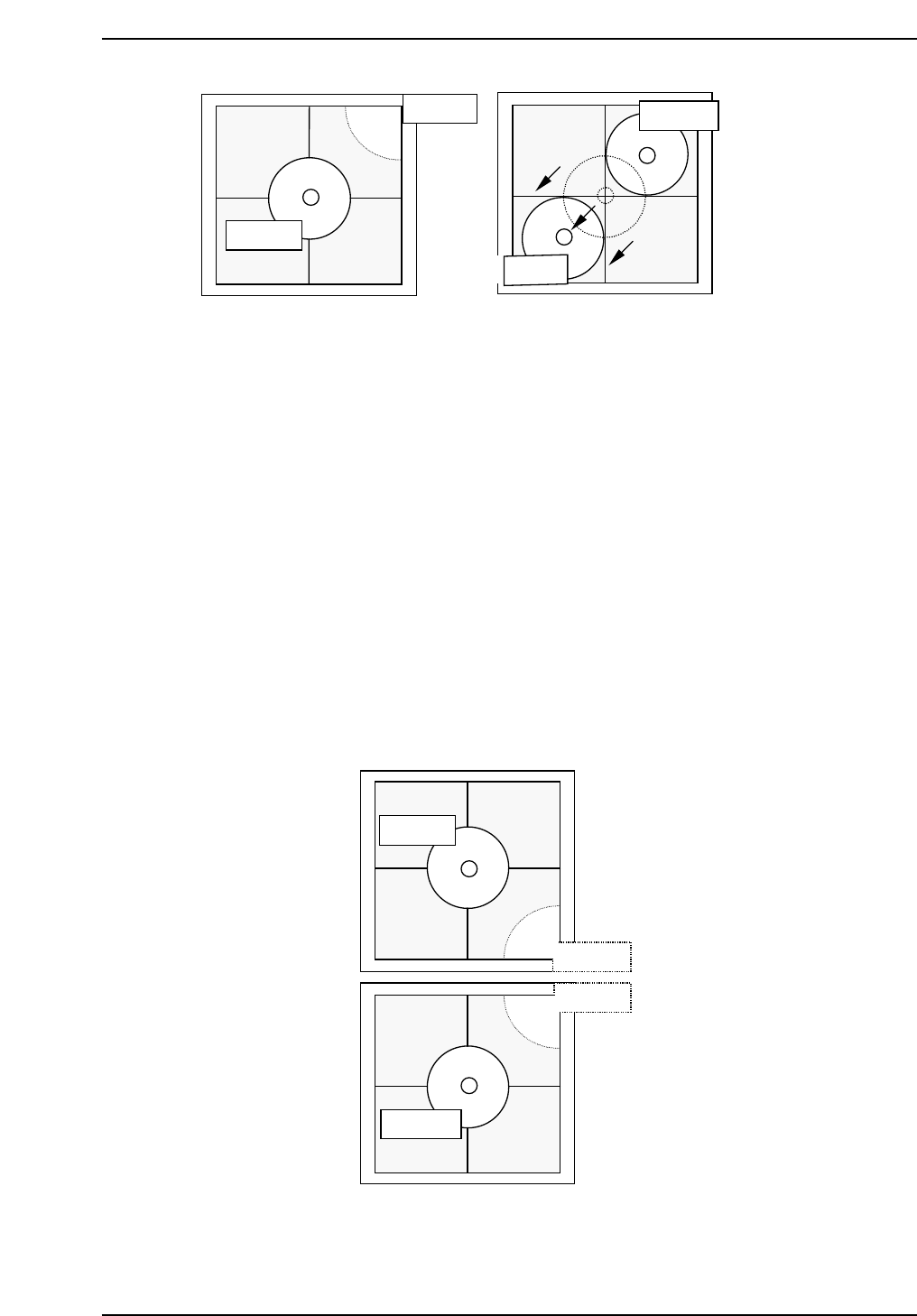
Note: It is possible to attach 8.0 mm backlight disks to holders A, B, C and D when using small
nozzles. As for larger disks, (17.0 backlight disks), they should be attached to holders A
and D and are referred to as nozzles E and F. Therefore, nozzles A and E, D and F use
the same holders. Separate Proper data measurement if necessary.
7. Press [SET] → [PROPER] → ID No. → [PM] → select the module →
[FINISH] → [Part Camera] → [Crosshair display] to display a real image
of the nozzle on the monitor.
8. Attach a 1.3 diameter nozzle to holder E (A) and F (D).
9. Use the inching keys to move reference nozzle E to the camera center
10. Press [Part Camera] → [Camera Center] → Select the nozzle E → [SET].
11. Press [Part Camera] → [Camera Center] → Select the nozzle F → [SET].
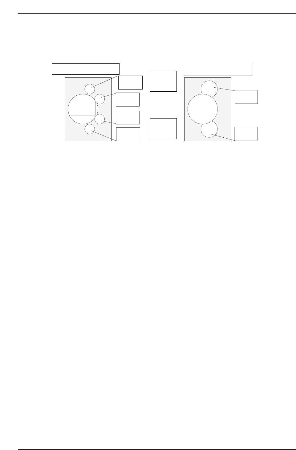
QP132T6006
Nozzle E
Nozzle B
Nozzle C
Nozzle F
QP132T6005
Nozzle C
Nozzle C
Nozzle D
Nozzle D
Chapter 6
6.2 Measuring Parts Camera Proper Data and Adjustment
Edition 1.1 6-5 QP-132 Level 3 Tutorial
6.2.3 Nozzle_A Holder Center
Note: This measures nozzle center and replaces the Proper data.
1. Attach a 1.3 diameter nozzle to holder A, B, C and D.
2. Press [PROGRAM] → [CHANGE] → Select program PORP_8 to the
foreground.
3. Press [AUTO] to transmit the program to the PMC .
4. Press [SET] → [PROPER] → ID No. → [PM] → select the module →
[FINISH] → [Part Camera] → [CALIB CNTR] → [In turn meas] →
[EXECUTE] → Enter a starting PM No. and final PM No. → START.
5. Attach a 1.3 diameter nozzle to holder E (A) and F (D).
6. Press [PROGRAM] → [CHANGE] → Select program to PORP_17 to the
foreground.
7. Press [AUTO] to transmit the program to the PMC.
8. Press [SET] → [PROPER] → ID No. → [PM] → Select the module. →
[FINISH] → [Part Camera] → [CALIB CNTR] → [In turn meas] →
[EXECUTE] → Enter a starting PM No. and final PM No. → START.
Q gear
↑
QP132T6007
View from top of X-axis head
Nozzle A
Nozzle B
Nozzle C
Nozzle D
Nozzle E
Nozzle F
(M/C rear)
↓
(M/C front)
View from top of X-axis head
Chapter 6
6.2 Measuring Parts Camera Proper Data and Adjustment
Edition 1.1 6-6 QP-132 Level 3 Tutorial

6.2.4 Nozzle Bend
Note: This measures nozzle bend and does not replace the Proper data.
1. [SET] → [MANUAL] → [NOZZLE] → [CALIB. CNTR] → [In turn meas]
or [Simult meas] → [EXECUTE] → Enter a starting PM No. and final PM
No. → START.
6.2.5 Nozzle_D Offset
Note: Calibrate the offset value for nozzles B, C and D from reference nozzle A, and the offset
value from nozzle F to nozzle E.
Camera Center and Nozzle Center must be measured before this calibration. The offset
between nozzles use the Nozzle Center value as reference.
1. Attach 1.3 diameter nozzle to each holder.
2. Press [SET] → [PROPER] → ID No. → [PM] → select the module →
[FINISH] → [Part Camera] → [OFF SET] → [EXECUTE] to activate auto-
calibration.
Chapter 6
6.2 Measuring Parts Camera Proper Data and Adjustment
Edition 1.1 6-7 QP-132 Level 3 Tutorial