00193802-01.pdf - 第108页
3 Technical data User Manual SIP LACE CF 3.12 PCB conveyor Software version SR. 101.xx 06/2003 US Edition 108 3.12. 2 T echnical dat a 3 PCB form at (length x wi dth) 50 mm x 5 0 mm to 508 mm x 460 mm (2" x 2 "…
User Manual SIPLACE CF 3 Technical data
Software version SR.101.xx 06/2003 US Edition 3.12 PCB conveyor
107
3.12 PCB conveyor
3.12.1 Structure of the PCB conveyor
The placement machine is supplied with a PCB conveyor. The left or the right side of the PCB
conveyor can be used as the stationary side, as required.
3
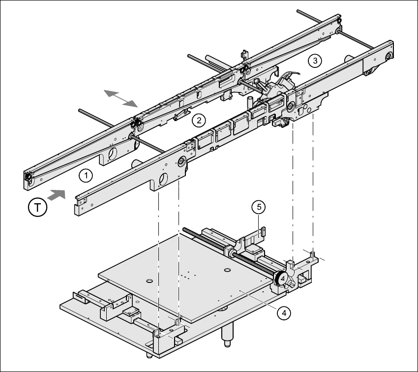
Fig. 3.12 - 1 PCB conveyor
3
(1) input conveyor
(2) center conveyor
(3) output conveyor
(4) lifting table
(5) width adjustment
(T) Direction of PCB transport

3 Technical data User Manual SIPLACE CF
3.12 PCB conveyor Software version SR.101.xx 06/2003 US Edition
108
3.12.2 Technical data
3
PCB format
(length x width)
50 mm x 50 mm to 508 mm x 460 mm
(2" x 2" to 20" x 18")
Long board: length up to 610 mm (24") (available upon
request)
PCB thickness 0.5 mm to 4.5 mm
Max. PCB warpage Up: 4.5 mm - PCB thickness
On bottom: 0.5 mm + PCB thickness
Clearance on PCB underside 25 mm (standard), 40 mm (option)
PCB transport height 830 mm ± 15 mm (standard)
900 mm ± 15 mm (optional)
930 mm ± 15 mm (optional)
950 mm ± 15 mm (SMEMA: optional)
Fixed conveyor side Right (standard), left (optional)
Type of interface Siemens
SMEMA
Component-free PCB handling edge 3 mm
PCB changeover time 2.5 s
Ink spot recognition Possible
Automatic width adjustment Possible
User Manual SIPLACE CF 4 Setting up the placement system
Software version SR.101.xx 06/2003 US Edition 4.1 Transport configuration and infrastructure
109
4 Setting up the placement system
4.1 Transport configuration and infrastructure
4
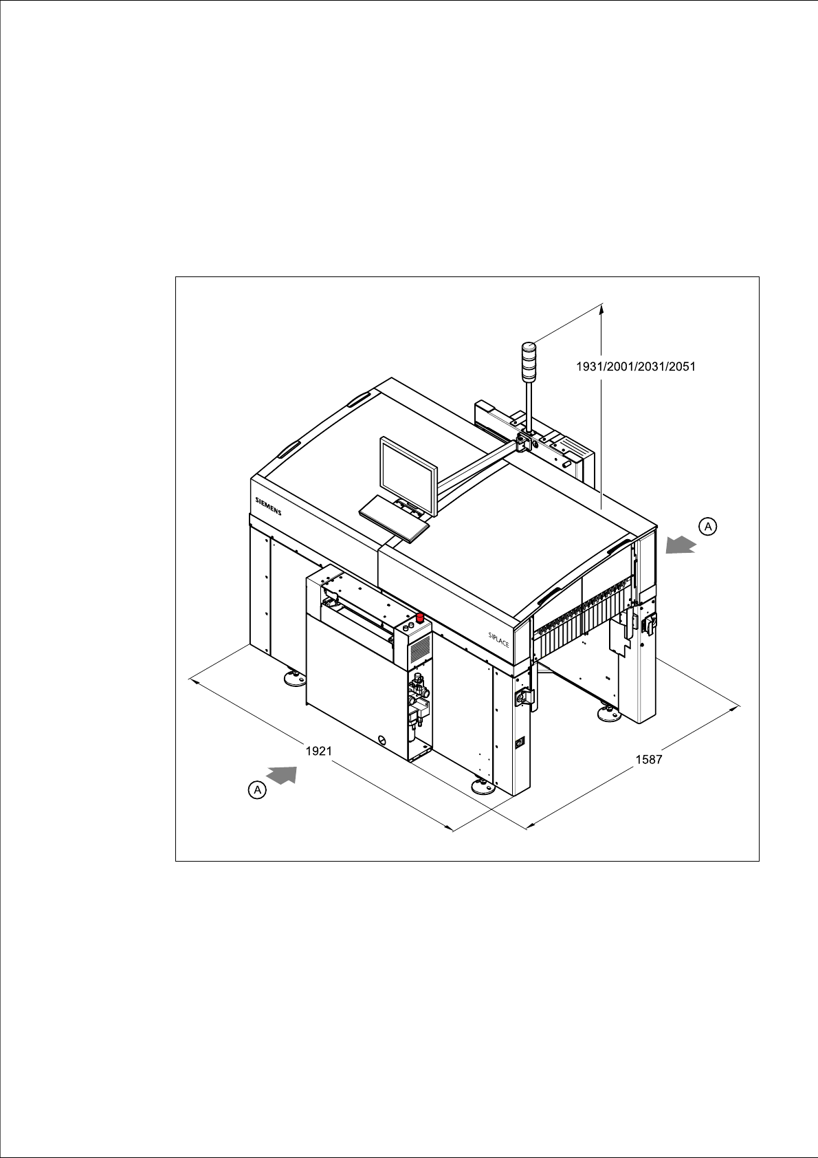
Fig. 4.1 - 1 Dimensions of the placement system during transportation and setting
up in millimeters
4
(A) Points for attaching the fork-lift truck (fork length 1600 mm)
(1) Input conveyor
(2) Output conveyor