00193802-01.pdf - 第153页
User Manual SIPLAC E CF 6 Component han dling Software version SR.101.xx 06/2003 US Edition 6.3 Setting up the feeders 153 6.3 Setting up the feeders 6.3.1 Prep aring t he component f eed er t able and feeder for set-up …
6 Component handling User Manual SIPLACE CF
6.2 Technical data for the feeders Software version SR.101.xx 06/2003 US Edition
152
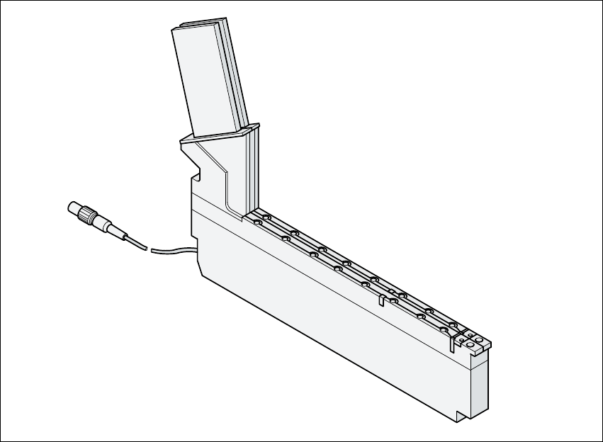
6.2.13 Bulk case feeder
Fig. 6.2 - 13 Bulk case feeder
6
Part no. 00142318-xx
29 mm wide 6
Tracks per feeder 2 6
Assigned locations 1 6
Maximum number of feeders 2 x 20 6
Stock of components up to 50,000 6
Feeding rails 0402 / 0.35 mm high part no. 00142319-xx 6
0402 / 0.5 mm high part no. 00142320-xx 6
0603 / 0.45 mm high part no. 00142321-xx 6
0603 / 0.80 mm high part no. 00142322-xx 6
0805 / 0.45 mm high part no. 00142323-xx 6
0805 / 0.60 mm high part no. 00142324-xx 6
0805 / 0.85 mm high part no. 00142325-xx 6
0805 / 1.25 mm high part no. 00142326-xx 6
Micro Melf / 1.05 ± 0.05 mm part no. 00142327-xx 6
Mini Melf / 1.40 ± 0.1 mm part no. 00142328-xx 6
Cycle time < 60 ms 6
User Manual SIPLACE CF 6 Component handling
Software version SR.101.xx 06/2003 US Edition 6.3 Setting up the feeders
153
6.3 Setting up the feeders
6.3.1 Preparing the component feeder table and feeder for set-up
Æ Select the setting range for the feeder to be used (see Vibrator configuration).
Æ Move the placement head to the waiting position and press the emergency stop button.
Æ Open the protective covers.
Æ Clean the contact surface for the feeders and the contact surface for the feeders on the com-
ponent table.
RISK OF INJURY
Avoid removing components from the magnetic rail of the component table with your fingers.
You may hurt yourself with tiny splinters of metal. 6
Æ Remove loose components with a short-bristled brush.
Æ Handle the feeders carefully when you insert them into or remove them from the component
table. Do not allow the supporting surfaces of the feeders to bang against the edges of the
component table.
Æ Place the feeder on the previously selected track on the component table (see Vibrator config-
uration).
6.3.2 Inserting the feeder
Æ Insert the feeder so that the back of the feeder is held by the centering ball and the front is fixed
in place by the corresponding centering pin on the component table. Make sure that the feeder
is placed on the component table in the correct position for its width.
Æ Check that the feeder is firmly seated on the component table.
Æ Connect the feeder plug to the socket beneath the location.
PLEASE NOTE 6
When you connect the feeder, make sure that you use the right socket for the location since
the feeder receives the control pulse via this socket. The feeder may not work correctly if it
is not connected to the right socket. 6
Æ Close the protective covers, release the emergency stop button and switch the controller on
again.
6 Component handling User Manual SIPLACE CF
6.3 Setting up the feeders Software version SR.101.xx 06/2003 US Edition
154
Æ Carry out a refill check if necessary.
Æ Continue placement.
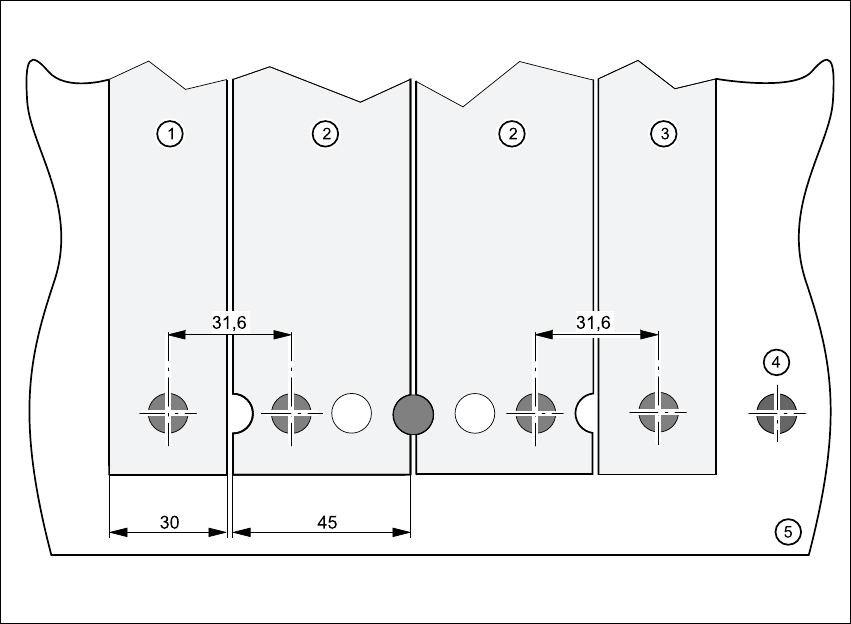
Fig. 6.3 - 1 Inserting 30 or 45 mm wide feeders on the component feeder table
6
(1) Feeder, 30 mm wide
(2) Feeder, 45 mm wide
(3) Feeder, 30 mm wide
(4) Centering ball
(5) Component feeder table