00193802-01.pdf - 第163页
User Manual SIPLAC E CF 6 Component han dling Software version SR.101.xx 06/2003 US Edition 6.6 Waffle-pack changer 163 6.6 W affle-p ack changer 6.6. 1 Ove rview Fig. 6.6 - 1 Waffle-pack changer on the SIPLACE CF 6 (1) …
6 Component handling User Manual SIPLACE CF
6.5 Used tape cutter Software version SR.101.xx 06/2003 US Edition
162
PLEASE NOTE 6
On SIPLACE automatic placement systems, only use the tape feeders specified for these ma-
chines. The used tape channel which removes the used tape is located upstream of the feeders.6
Æ Insert the tape into the feeder as described in the corresponding section.
Æ Guide the used tape into the used tape channel of the cutter as described in Fig. 6.5 - 2.
The used tape guide channels are located upstream of the feeders. They are positioned directly
above the used tape cutters.
The tape is automatically guided through the used tape guide channel into the used tape cutter
below. There, the tape is shredded by the pneumatically-actuated cutting blade. The waste tape
then passes via the waste tape chute into the waste container of the component trolley.
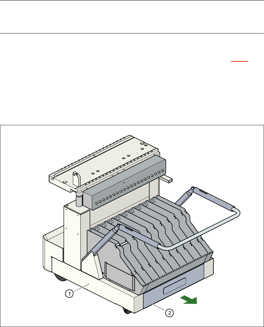
Fig. 6.5 - 3 Pull-out waste tape container in the component trolley
6
(1) Component trolley
(2) Pull-out waste tape container
User Manual SIPLACE CF 6 Component handling
Software version SR.101.xx 06/2003 US Edition 6.6 Waffle-pack changer
163
6.6 Waffle-pack changer
6.6.1 Overview
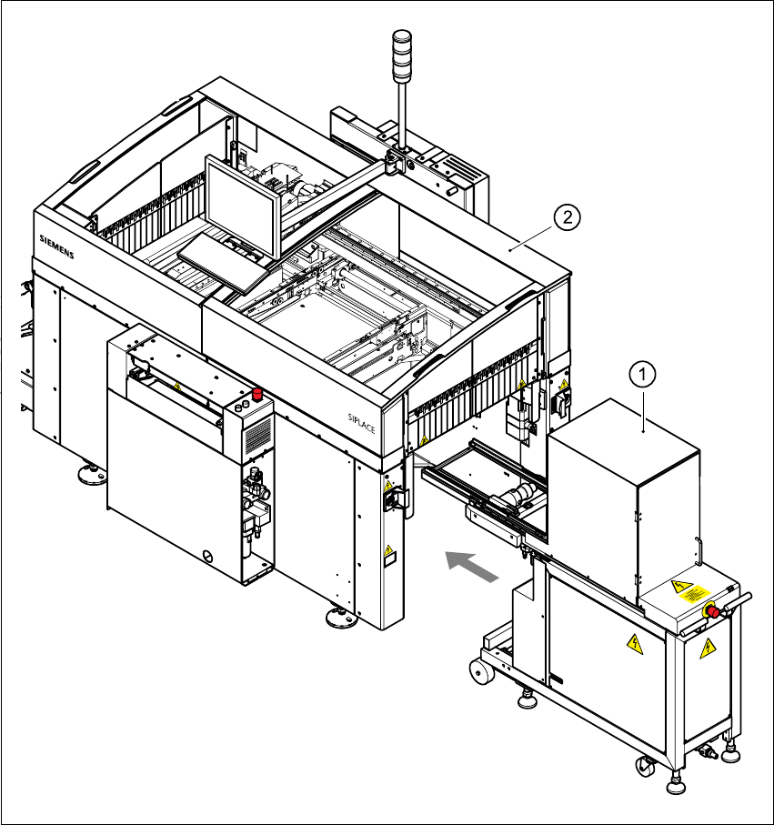
Fig. 6.6 - 1 Waffle-pack changer on the SIPLACE CF
6
(1) Waffle-pack changer at location 1
(2) SIPLACE CF

6 Component handling User Manual SIPLACE CF
6.6 Waffle-pack changer Software version SR.101.xx 06/2003 US Edition
164
6.6.2 General
The space required by waffle trays is relatively large in comparison to the component density.
The low component capacity also requires the waffle trays to be changed frequently, which
means that the placement sequence has to be interrupted if the trays are changed manually.
The use of a waffle-pack changer eliminates this unnecessary time loss since the waffle trays are
stored and automatically changed. Programmable, random access to up to 28 waffle trays also
increases the range of components that can be made available.
PLEASE NOTE 6
The waffle-pack changer does not fill the entire width of the component feeder table. It leaves 10
locations on the right-hand side of the table that could be used for ten 8 mm feeders, for example.6
6.6.3 Principle of the waffle-pack changer
The waffle-pack changer can be used to store and change up to 28 waffle trays fully automati-
cally. The magazine carriers (levels) for the waffle-pack trays are numbered consecutively in
ascending order from bottom to top (1 - 28).
The magazine storage unit moves vertically to the selected level within the travelling range of the
horizontal axis. The horizontal axis then grabs the magazine carrier from the level, and carries it
to within the access range of the placement head.
Fig. 6.6 - 2
below illustrates the principle of the waffle-pack changer.