00193802-01.pdf - 第48页
2 Operational safety User Manual SIPLACE CF 2.5 Safety equipment Sof tware version SR.101.xx 06/2003 US E dition 48 2.5.3 Emergency stop buttons, protec tive cove r switches .. . 2 Fig. 2.5 - 4 Location of the buttons an…
User Manual SIPLACE CF 2 Operational safety
Software version SR.101.xx 06/2003 US Edition 2.5 Safety equipment
47
2.5.2 Guard on the input/output belt
WARNING
The guard must always be set to the height of the PCB to be processed. Ensure that the gap
between the guard and the safety bar is as small as possible. 2
Guards are fitted on the input and output belts of the PCB conveyor.
The height of the guard must be set using the slots so that the processed PCB can travel
through.
2
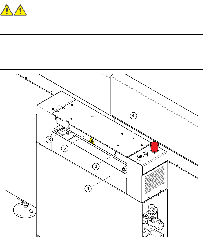
Fig. 2.5 - 3 Guard on the placement machine
(1) Safety bar (fixed)
(2) Guard (adjustable)
(3) Slots for adjusting the height
(4) Cover
2 Operational safety User Manual SIPLACE CF
2.5 Safety equipment Software version SR.101.xx 06/2003 US Edition
48
2.5.3 Emergency stop buttons, protective cover switches ...
2
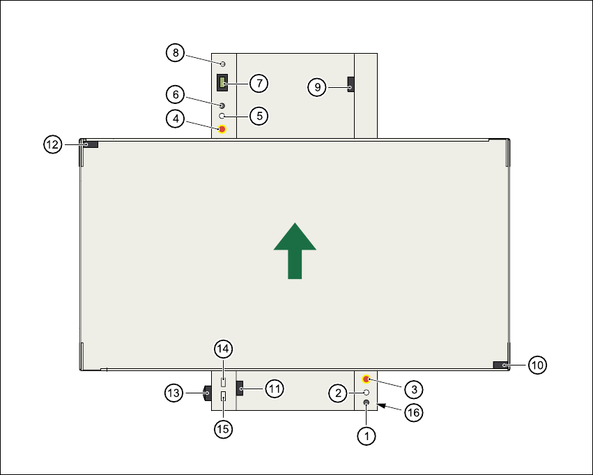
Fig. 2.5 - 4 Location of the buttons and protective contactor combinations K1, K2
2
(1) Stop button
(2) Start button
(3) Emergency stop button
(4) Emergency stop button
(5) Start button
(6) Stop button
(7) Component counter
(8) Key switch open:position 0 for normal mode
Key switch closed: position I for service purposes
(9) Protective cover switch (output conveyor, 00303617-xx)
(10) Protective cover switch (right, 00321417-xx)
(11) Protective cover switch (input conveyor, 00303614-xx)
(12) Protective cover switch (left, 00321416-xx)
User Manual SIPLACE CF 2 Operational safety
Software version SR.101.xx 06/2003 US Edition 2.5 Safety equipment
49
(13) Main power switch
(14) Protective contactor combination K1 at the power supply unit
(15) Protective contactor combination K2 at the power supply unit
(16) Compressed air unit
2.5.3.1 Functional description
Emergency stop button
When the emergency stop button is pressed (item 3 or item 4. in Fig. 2.5 - 4), the motor voltage
to the gantry axes is switched off. The gantry axes are no longer powered, and thus are not dan-
gerous.
PLEASE NOTE
Placement is interrupted and can then either be continued or canceled once the system is work-
ing correctly again. 2
Protective cover switch
If one of the protective covers is opened (see items 9, 10, 11, or 12 in Fig. 2.5 - 4), the gantry
axes will stop immediately. They are no longer powered, and thus are not dangerous.
Key-operated switch:
If the key switch (item 8 in Fig. 2.5 - 4) is closed (position I), the star can still be paced at low
speed while the protective covers are open. The gantry axes are no longer powered, and thus
are not dangerous.
PLEASE NOTE
The key switch remains open for normal mode, i.e. in the 0 position. 2
WARNING
The protective covers must only be opened, with the key switch closed (position I), by appropri-
ately qualified and trained personnel. 2