00193802-01.pdf - 第53页
User Manual SIPLAC E CF 2 Operational safety Software version SR.101.xx 06/2003 US Edition 2.5 Safety equipment 53 2.5.5 Guard on the component t able locations W A RNING 2 All loc ations m ust be equ ipped with feeders …
2 Operational safety User Manual SIPLACE CF
2.5 Safety equipment Software version SR.101.xx 06/2003 US Edition
52
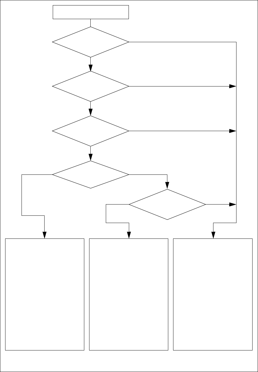
Fig. 2.5 - 5 Safety circuits
2
2
Active
K1 *) yes
K2 *) yes
Voltage
Y axis 155 V
X axis 155 V
Star axis 70 V
DP axis 30 V
Z axis 30 V
Active
PCB conveyor yes
Lifting table yes
PCB clamping yes
Width adjustment yes
PCB stopper yes
Used tape cutter yes
2
Active
K1 *) no
K2 *) yes
Voltage
Y axis 0 V
X axis 0 V
Star axis 10 V
DP axis 30 V
Z axis 30 V
Active
PCB conveyor yes
Lifting table no
PCB clamping no
Width adjustment yes
PCB stopper no
Used tape cutter no
2
Active
K1 *) no
K2 *) no
Voltage
Y axis 0 V
X axis 0 V
Star axis 10 V
DP axis 30 V
Z axis 30 V
Active
PCB conveyor no
Lifting table no
PCB clamping no
Width adjustment no
PCB stopper no
Used tape cutter no
2
Start button pressed?
2
EMERGENCY STOP
button pressed?
Compressed air
min. 0.5 MPa
(5.0 bar)?
No
Protective cover open ?
No
Component
trolley safety circuit
interrupted?
Yes
No
No
Yes
Yes
No
Yes
Yes
Key switch
closed (positionI)?
*) K1, K2 protective contactor combination
User Manual SIPLACE CF 2 Operational safety
Software version SR.101.xx 06/2003 US Edition 2.5 Safety equipment
53
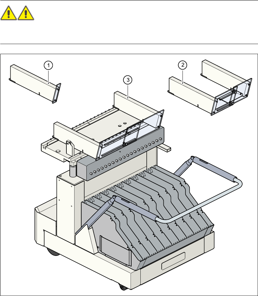
2.5.5 Guard on the component table locations
WARNING 2
All locations must be equipped with feeders in order to guarantee operational reliability. If there
are not enough feeders available, a guard ("dummy feeder") must be fitted in place of the feeder.2
2
Fig. 2.5 - 6 Guard
2
(1) Guard for 1 location part no. 00116961-01
(2) Guard for 6 to 10 locations part no. 00116962-01
(3) Guard for 11 to 20 locations part no. 00116963-01
2 Operational safety User Manual SIPLACE CF
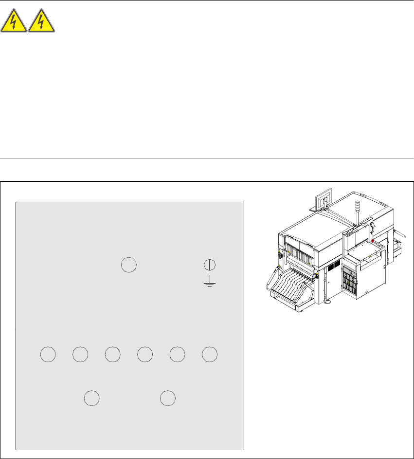
2.6 Residual voltages and discharge times in the placement machine Software version SR.101.xx 06/2003 US Edition
54
2.6 Residual voltages and discharge times in the
placement machine
When the emergency stop button is pressed or the placement system is switched off, the electro-
lytic capacitors quickly discharge to safe residual voltage levels via switched resistors on the dis-
charge board (00308443-xx).
The voltages can be tapped off at test sockets 001 - 009 on the voltmeter unit in the servo unit.
WARNING 2
Automatic placement systems from the SIPLACE family are powered with 3 x 400 VAC (3 x 208
VAC for the U.S.A. version) ± 5 %, 50/60 Hz main power voltage. This means that some parts of
the system carry potentially lethal voltages - even when switched off at the main power switch.
Death, serious injury or considerable damage may result if these automatic placement systems
are handled incorrectly. Always follow the applicable accident prevention and DIN regulations
(particularly EN 60204, part 1).
The guard over the servo unit must ONLY be opened by appropriately qualified and trained per-
sonnel. 2
2
Fig. 2.6 - 1 Test sockets on the voltage measuring unit in the servo unit
GND
007
001 002 003 004 005 006
008 009
70VDC/
10VDC
30VDC 24VDC 12VDC 5VDC
70VDC
155VDC/0VDC
30VDC
unswitched
switched