00193802-01.pdf - 第56页
2 Operational safety User Manual SIPLACE CF 2.7 Disabling the compressed air supply and discharging the pressure Software version SR.101.xx 06/2003 US Edition 56 2.7 Disabling the compresse d air supply and di scharg- in…
User Manual SIPLACE CF 2 Operational safety
Software version SR.101.xx 06/2003 US Edition 2.6 Residual voltages and discharge times in the placement machine
55
2.6.1 Operating voltages, residual voltages and discharge times after pressing
the emergency stop button
2
2.6.2 Residual voltages and discharge times after switching off at the main switch
2
CAUTION
To avoid losing data, evaluate the following criteria before switching off your automatic placement
system (apart from in emergencies):
– Has the placement system finished transmitting machine, setup and panel data?
– Has the placement system finished processing the PCB?
– Has the placement system completed the run-up phase?
– Has the Windows XP operating system been shut down correctly? 2
Test socket 00X
measured at 007
(GND)
Voltage in normal
mode
Residual
voltage after
EMERG. STOP
Discharge times of
electrolytic capacitors at
12 VDC
001 70 VDC 10 VDC < 2 sec
002 30 VDC 30 VDC –
003 30 VDC < 12 VDC < 2 sec
004 24 VDC 24 VDC –
005 12 VDC 12 VDC –
006 5 VDC 5 VDC –
008 70 VDC 10 VDC < 2 sec
009 155 VDC 10 VDC < 1 sec
Tab. 2.6 - 1 Operating voltages, residual voltages and discharge times after pressing the emergency stop button
Test socket 00X
measured at 007 (GND)
Residual voltage when
main power switch is off
Discharge times of electrol.
capacitors at 12 VDC
001 < 12 VDC < 2 sec
002 < 12 VDC < 2 sec
003 < 12 VDC < 2 sec
004 0 VDC –
005 0 VDC –
006 0 VDC –
008 < 12 VDC < 2 sec
009 < 12 VDC < 1 sec
Tab. 2.6 - 2 Residual voltages and discharge times after switching off at the main switch
2 Operational safety User Manual SIPLACE CF
2.7 Disabling the compressed air supply and discharging the pressure Software version SR.101.xx 06/2003 US Edition
56
2.7 Disabling the compressed air supply and discharg-
ing the pressure
2
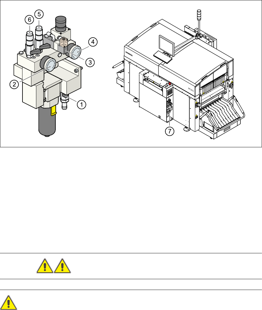
Fig. 2.7 - 1 Compressed air unit on the placement system
2
(1) Shut-off valve lever in the CLOSED position
(2) Working pressure gauge
(3) Solenoid valve for venting the tape cutter during an emergency stop
(4) Pressure gauge for the PCB stopper working pressure
(5) Compressed air supply, gantry 2
(6) Compressed air supply, gantry 1
(7) Position of the compressed air unit
WARNING Never disconnect compressed air lines while they are pressurized. 2
CAUTION 2
When the machine is switched on, do not use the stop valve to interrupt the compressed air supply
for more than 30 minutes. If you need to shut off the pneumatic system for longer in order to carry
out preventive maintenance or servicing work, you must switch the placement system off at the

User Manual SIPLACE CF 2 Operational safety
Software version SR.101.xx 06/2003 US Edition 2.7 Disabling the compressed air supply and discharging the pressure
57
main switch and disconnect it from the power supply. 2
The compressed air working pressure is set to 0.52 MPa (5.2 bar). It may fluctuate between 0.5
MPa (5.0 bar) and 0.53 MPa (5.3 bar). The position of the compressed air unit is indicated by
item 5 in Fig. 2.7 - 1
. The compressed air supply to the machine can be interrupted using the
shutoff valve (item 1 in Fig. 2.7 - 1
).
– You must remove the cover plate to use the shut-off valve.
– Turn the lever on the shut-off valve (item 1 in Fig. 2.7 - 1
) from the vertical to the horizontal
position.
– Watch the working pressure gauge (item 2 in Fig. 2.7 - 1
) and the pressure gauge for the com-
pressed air supply to the stopper (item 4 in Fig. 2.7 - 1
). When the automatic placement system
is switched on, the pressure discharges to 0 MPa (0 bar) within 1 minute.