00193802-01.pdf - 第70页
3 Technical data User Manual SIP LACE CF 3.1 Description of the m achine Software v ersion SR.101.xx 06/2003 US Edition 70 3.1.1 T echnical dat a - m achine ov erview 3 *) The CF can be equipped to place 0201 c omponents…
User Manual SIPLACE CF 3 Technical data
Software version SR.101.xx 06/2003 US Edition 3.1 Description of the machine
69
3
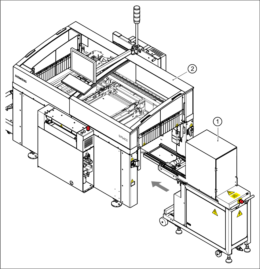
Fig. 3.1 - 2 CF overall view with waffle-pack changer
3
(1) Waffle-pack changer
(2) SIPLACE CF

3 Technical data User Manual SIPLACE CF
3.1 Description of the machine Software version SR.101.xx 06/2003 US Edition
70
3.1.1 Technical data - machine overview
3
*) The CF can be equipped to place 0201 components. Please consult the factory if you require this.
Placement procedure Collect&Place / Pick&Place
Component range
*)
6-segment Collect&Place head
Max. component height
Pick&Place head
Max. component height
From 0.6 mm x 0.3 mm to 18.7 mm x 18.7 mm (0201
to PLCC44, SO32, DRAM)
6 mm (10.7 mm available upon request)
Up to 55 mm x 55 mm
≤ 13.5 mm - PCB thickness - PCB warpage
(
≤ 20 mm - PCB thickness - PCB warpage available
upon request)
Maximum placement rate (Benchmark)
6-segment Collect&Place head
Pick&Place head
9.000 components/h
1.800 components/h
6-segment Collect&Place head
Angular accuracy
< Idx id="31"/>Placement accuracy
± 0.7°/ 4 σ
± 90 µm / 4 σ
Pick&Place head
Angular accuracy
Placement accuracy
± 0.07°/ 4 σ
± 50 µm / 4 σ
PCB format
(length x width) 50 mm x 50 mm to 508 mm x 460 mm
(2" x 2" to 20" x 18")
Long board: length up to 610 mm (24") (available upon
request)
PCB thickness 0.5 mm to 4.5 mm
PCB changeover time 2.5 sec
Feeder capacity 118 tracks à 8 mm
Component supply
Types of feeder
Component trolley, waffle-pack changer
Component tapes, stick magazines, bulk cases, man-
ual tray (see chapter 6
)
Operating system Microsoft Windows XP / RMOS
Connection Inline or stand alone
Space required 4 m² / module

User Manual SIPLACE CF 3 Technical data
Software version SR.101.xx 06/2003 US Edition 3.2 The line concept
71
3.2 The line concept
3.2.1 Overview
Up to 5 placement machines from the SIPLACE Compact families can be linked to form a line.
3.2.2 Technical data – line concept
3
System SIPLACE placement lines
Modules SIPLACE CS, SIPLACE CF
Peripherals Input/output stations
Screen printers
Soldering ovens
Inspection stations, etc.
Component range From 0201 to 18.7 mm x 18.7 mm (CS)
From 0201 to 55 mm x 55 mm (CF)
PCB conveyor Automatic width adjustment
PCB format (length x width) 50 mm x 50 mm to 508 mm x 460 mm
(2" x 2" to 20" to 18")
Placement rate Depends how modules are connected in series
Line software SIPLACE C Pro
Space required 4 m² / module