00193802-01.pdf - 第71页
User Manual SIPLAC E CF 3 Technical data Software version SR.101.xx 06/2003 US Edition 3.2 The line concept 71 3.2 The line concept 3.2. 1 Ove rview Up to 5 p lacement ma chine s from the S IPLACE Com pact famili es can …

3 Technical data User Manual SIPLACE CF
3.1 Description of the machine Software version SR.101.xx 06/2003 US Edition
70
3.1.1 Technical data - machine overview
3
*) The CF can be equipped to place 0201 components. Please consult the factory if you require this.
Placement procedure Collect&Place / Pick&Place
Component range
*)
6-segment Collect&Place head
Max. component height
Pick&Place head
Max. component height
From 0.6 mm x 0.3 mm to 18.7 mm x 18.7 mm (0201
to PLCC44, SO32, DRAM)
6 mm (10.7 mm available upon request)
Up to 55 mm x 55 mm
≤ 13.5 mm - PCB thickness - PCB warpage
(
≤ 20 mm - PCB thickness - PCB warpage available
upon request)
Maximum placement rate (Benchmark)
6-segment Collect&Place head
Pick&Place head
9.000 components/h
1.800 components/h
6-segment Collect&Place head
Angular accuracy
< Idx id="31"/>Placement accuracy
± 0.7°/ 4 σ
± 90 µm / 4 σ
Pick&Place head
Angular accuracy
Placement accuracy
± 0.07°/ 4 σ
± 50 µm / 4 σ
PCB format
(length x width) 50 mm x 50 mm to 508 mm x 460 mm
(2" x 2" to 20" x 18")
Long board: length up to 610 mm (24") (available upon
request)
PCB thickness 0.5 mm to 4.5 mm
PCB changeover time 2.5 sec
Feeder capacity 118 tracks à 8 mm
Component supply
Types of feeder
Component trolley, waffle-pack changer
Component tapes, stick magazines, bulk cases, man-
ual tray (see chapter 6
)
Operating system Microsoft Windows XP / RMOS
Connection Inline or stand alone
Space required 4 m² / module

User Manual SIPLACE CF 3 Technical data
Software version SR.101.xx 06/2003 US Edition 3.2 The line concept
71
3.2 The line concept
3.2.1 Overview
Up to 5 placement machines from the SIPLACE Compact families can be linked to form a line.
3.2.2 Technical data – line concept
3
System SIPLACE placement lines
Modules SIPLACE CS, SIPLACE CF
Peripherals Input/output stations
Screen printers
Soldering ovens
Inspection stations, etc.
Component range From 0201 to 18.7 mm x 18.7 mm (CS)
From 0201 to 55 mm x 55 mm (CF)
PCB conveyor Automatic width adjustment
PCB format (length x width) 50 mm x 50 mm to 508 mm x 460 mm
(2" x 2" to 20" to 18")
Placement rate Depends how modules are connected in series
Line software SIPLACE C Pro
Space required 4 m² / module
3 Technical data User Manual SIPLACE CF
3.3 Electrical and pneumatic connection points Software version SR.101.xx 06/2003 US Edition
72
3.3 Electrical and pneumatic connection points
3
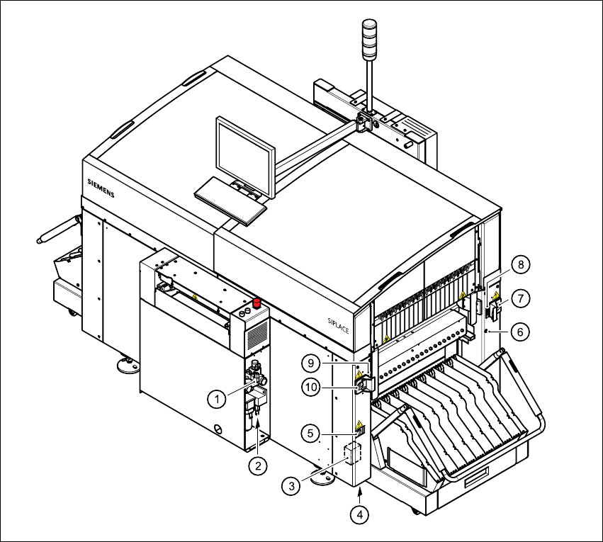
Fig. 3.3 - 1 Electrical and pneumatic connection points on the placement system- part 1
(1) Compressed air unit
(2) Connection for compressed air line
(3) Main power filter Z1
(4) Hole for power cable
(5) Service socket
(6) Compressed air connection for component trolleys
(7) Power supply connection for component trolley
(8) Communications connection for component trolley
(9) Communications connection for waffle-pack changer
(10) Power supply connection for waffle-pack changer