00193802-01.pdf - 第96页
3 Technical data User Manual SIP LACE CF 3.10 Vision modules Sof tware version SR.101.xx 06/2003 US Edition 96 3.10.2 Component camera (st andard ca mera) on the 6-segm ent Collect&Place head 3.10.2.1 Str ucture 3 Fi…
User Manual SIPLACE CF 3 Technical data
Software version SR.101.xx 06/2003 US Edition 3.10 Vision modules
95
3.10 Vision modules
3.10.1 Description
Each placement system has
– one component vision module on the 6-segment Collect&Place head,
– one fine pitch vision camera on the machine base and
– one PCB vision module on the underside of the X axis gantry.
The vision analysis unit is located in the control unit for the placement system. The component
vision module is used to determine:
– the precise position of the components at the nozzle and
– the geometry of the package form.
The PCB vision module uses fiducials on the PCBs to determine:
– the position of the PCB,
– its rotation angle
– and the PCB skew.
The PCB vision module also uses fiducials on the feeders to determine the exact pick-up position
of components. This is particularly important for small components.
3 Technical data User Manual SIPLACE CF
3.10 Vision modules Software version SR.101.xx 06/2003 US Edition
96
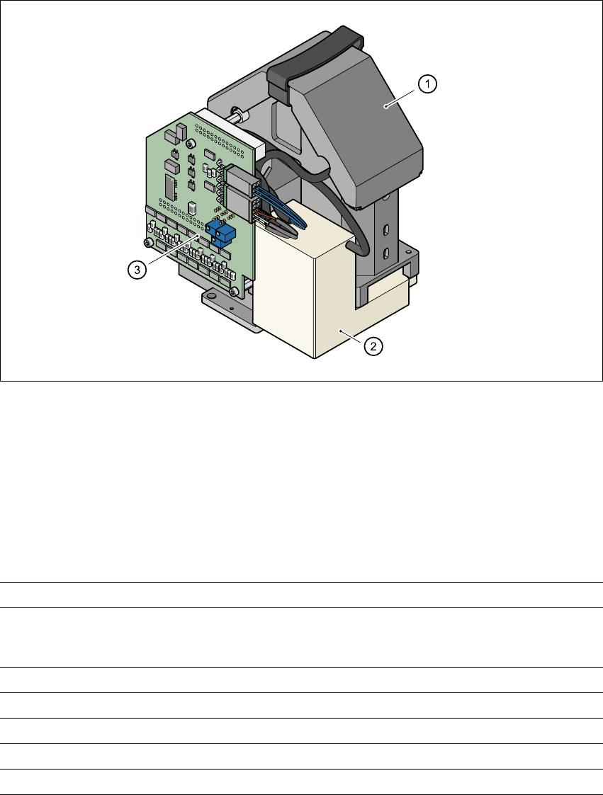
3.10.2 Component camera (standard camera) on the 6-segment Collect&Place
head
3.10.2.1 Structure
3
Fig. 3.10 - 1 Component camera (standard camera) on the 6-segment Collect&Place head
3
(1) Component camera, lens and illumination
(2) Camera amplifier
(3) Illumination control
3.10.2.2 Technical data
3
Max. component dimensions 0.6 mm x 0.3 mm to 18.7 mm x 18.7 mm
Range of components 0201 to PLCC44
including BGA, µBGA, flip-chip, TSOP, QFP
PLCC, SO to SO32, DRAM
Min. lead pitch 0.5 mm
Min. bump pitch 0.35 mm
Min. ball/bump diameter 0.2 mm
Field of vision 24 mm x 24 mm
Method of illumination Front-lighting (3 levels, programable as required)
User Manual SIPLACE CF 3 Technical data
Software version SR.101.xx 06/2003 US Edition 3.10 Vision modules
97
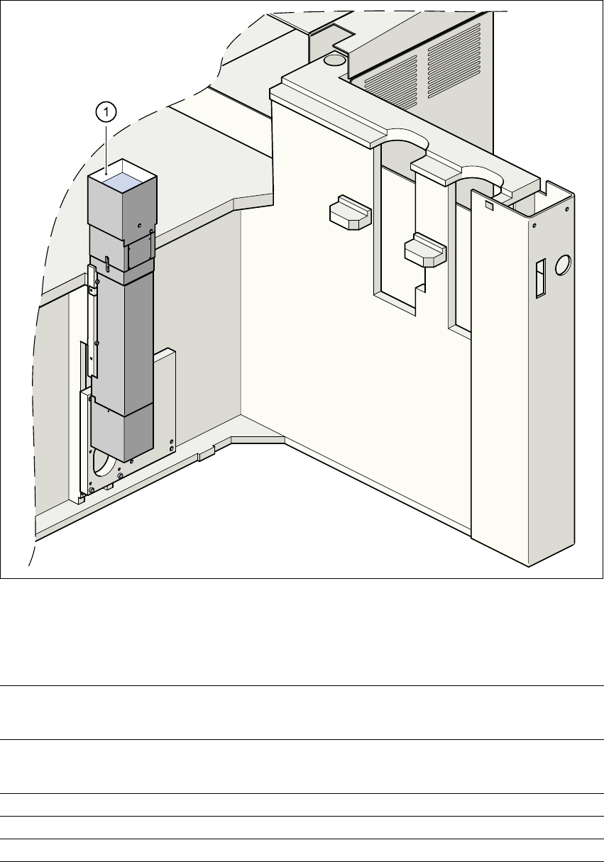
3.10.3 Fine-pitch camera for the Pick&Place head
3
Fig. 3.10 - 2 Fine-pitch camera for the Pick&Place head
(1) Fine-pitch camera for the Pick&Place head
3.10.3.1 Technical data
3
Max. component dimensions 32 mm x 32 mm (single measurement)
55 mm x 55 mm (multiple measurement)
(larger components possible upon request)
Range of components PLCC, LCCC, QFP, SO, BGA, flip-chip,
components with connectors up to 55 mm x 55 mm
(J leads and gull-wings, balls, bumps)
Min. lead pitch 0.4 mm
Field of vision 38 mm x 38 mm
Method of illumination Front-lighting (3 levels, programable as required)