00193802-01.pdf - 第98页
3 Technical data User Manual SIP LACE CF 3.10 Vision modules Sof tware version SR.101.xx 06/2003 US Edition 98 3.10. 4 PCB camera (st andard camera) 3.10.4.1 Str ucture 3 Fig. 3.10 - 3 PCB camera 3 (1) PCB camer a, lens …
User Manual SIPLACE CF 3 Technical data
Software version SR.101.xx 06/2003 US Edition 3.10 Vision modules
97
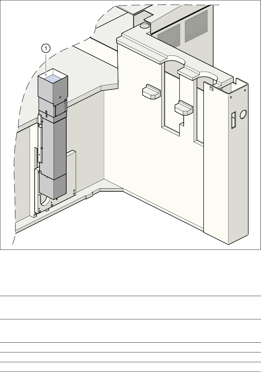
3.10.3 Fine-pitch camera for the Pick&Place head
3
Fig. 3.10 - 2 Fine-pitch camera for the Pick&Place head
(1) Fine-pitch camera for the Pick&Place head
3.10.3.1 Technical data
3
Max. component dimensions 32 mm x 32 mm (single measurement)
55 mm x 55 mm (multiple measurement)
(larger components possible upon request)
Range of components PLCC, LCCC, QFP, SO, BGA, flip-chip,
components with connectors up to 55 mm x 55 mm
(J leads and gull-wings, balls, bumps)
Min. lead pitch 0.4 mm
Field of vision 38 mm x 38 mm
Method of illumination Front-lighting (3 levels, programable as required)
3 Technical data User Manual SIPLACE CF
3.10 Vision modules Software version SR.101.xx 06/2003 US Edition
98
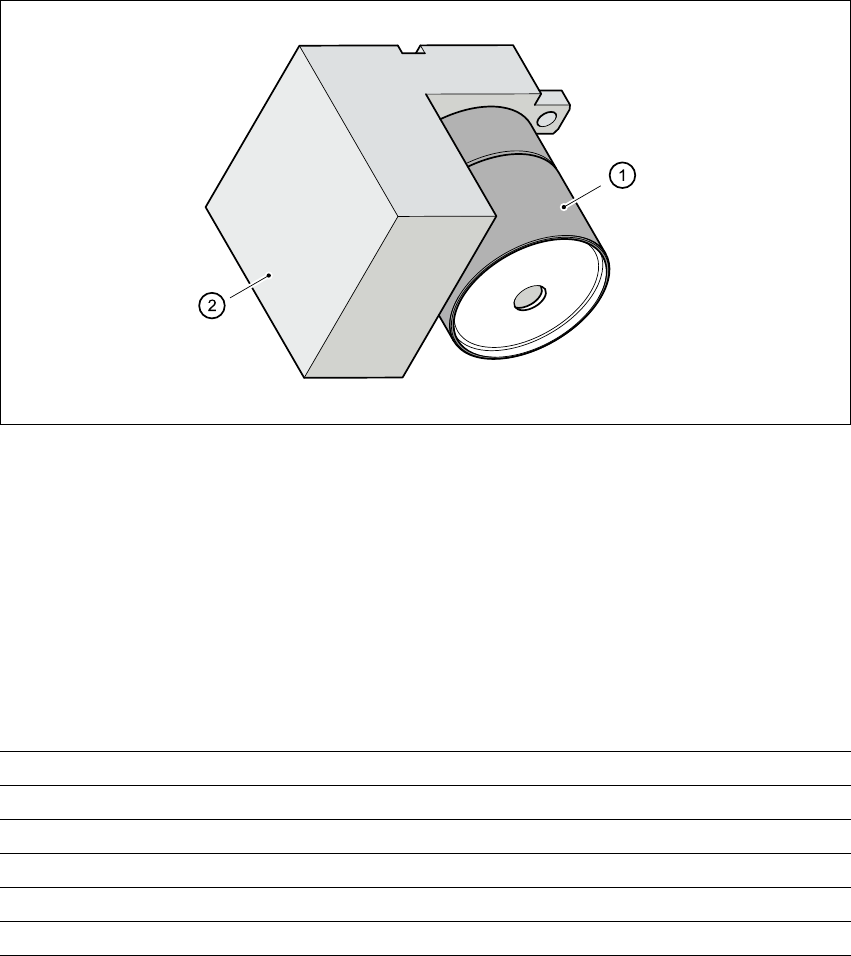
3.10.4 PCB camera (standard camera)
3.10.4.1 Structure
3
Fig. 3.10 - 3 PCB camera
3
(1) PCB camera, lens and illumination
(2) Camera amplifier
3.10.4.2 Technical data - PCB camera
3
Fiducials Up to 3 per placement program
Library size Up to 255 fiducial types - system fiducials 249
Image processing Geometric alignment
Method of illumination Front-lighting
Recognition time per fiducial/bad fiducial 0.4 s
Field of vision 5.7 mm x 5.7 mm

User Manual SIPLACE CF 3 Technical data
Software version SR.101.xx 06/2003 US Edition 3.11 Nozzle changer for the 6-segment Collect&Place head
99
3.11 Nozzle changer for the 6-segment Collect&Place
head
3.11.1 Overview
A nozzle changer for the 6-segment Collect&Place head may be installed to the left of the PCB
conveyor without losing any locations. This enables the nozzle configuration to be changed
quickly, thus allowing the Collect&Place head to be quickly adapted to the needs of the place-
ment process.
The nozzle changer consists of at least one, and up to five magazines, each with twelve nozzle
garages (see Fig. 3.11 - 1
). The magazines are seated on a common support. Each magazine is
centered using two parallel pins and fixed in place with a spring hook.
3.11.2 Technical data
3
Nozzle changer for the 6-segment Collect&Place head
Dimensions (length x width x height) 673 mm x 74 mm x 75 mm
Number of nozzle holders Min. 6 / max. 30
Nozzle types 9 xx
Time required to open and close the locking
plate < 200 ms
Capacity of the reject bin Approx. 50 nozzles
Pneumatic system Compressed air line 0.53 MPa (5.3 bar)