00193802-01.pdf - 第99页
User Manual SIPLAC E CF 3 Technical data Software version SR.101.xx 06/2003 US Edition 3.11 Nozzle changer for the 6-segment Collect&Place head 99 3.1 1 Nozzl e changer for the 6-segme nt Colle ct & Place head 3.…
3 Technical data User Manual SIPLACE CF
3.10 Vision modules Software version SR.101.xx 06/2003 US Edition
98
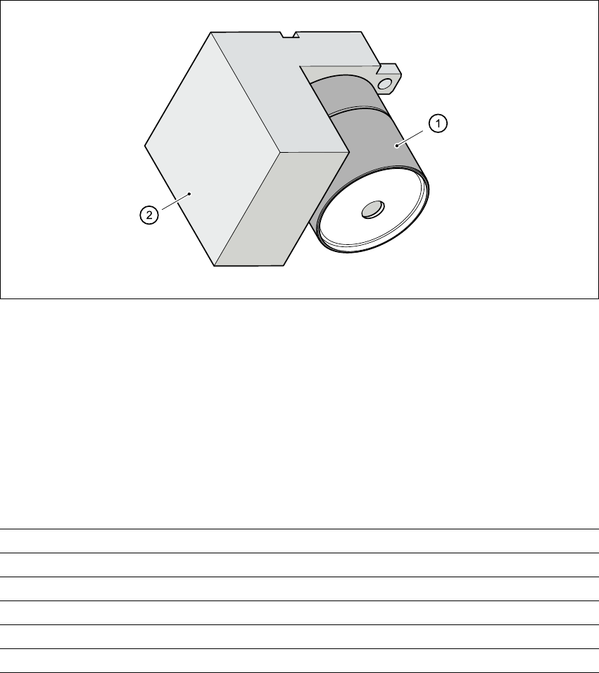
3.10.4 PCB camera (standard camera)
3.10.4.1 Structure
3
Fig. 3.10 - 3 PCB camera
3
(1) PCB camera, lens and illumination
(2) Camera amplifier
3.10.4.2 Technical data - PCB camera
3
Fiducials Up to 3 per placement program
Library size Up to 255 fiducial types - system fiducials 249
Image processing Geometric alignment
Method of illumination Front-lighting
Recognition time per fiducial/bad fiducial 0.4 s
Field of vision 5.7 mm x 5.7 mm

User Manual SIPLACE CF 3 Technical data
Software version SR.101.xx 06/2003 US Edition 3.11 Nozzle changer for the 6-segment Collect&Place head
99
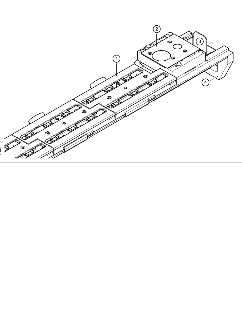
3.11 Nozzle changer for the 6-segment Collect&Place
head
3.11.1 Overview
A nozzle changer for the 6-segment Collect&Place head may be installed to the left of the PCB
conveyor without losing any locations. This enables the nozzle configuration to be changed
quickly, thus allowing the Collect&Place head to be quickly adapted to the needs of the place-
ment process.
The nozzle changer consists of at least one, and up to five magazines, each with twelve nozzle
garages (see Fig. 3.11 - 1
). The magazines are seated on a common support. Each magazine is
centered using two parallel pins and fixed in place with a spring hook.
3.11.2 Technical data
3
Nozzle changer for the 6-segment Collect&Place head
Dimensions (length x width x height) 673 mm x 74 mm x 75 mm
Number of nozzle holders Min. 6 / max. 30
Nozzle types 9 xx
Time required to open and close the locking
plate < 200 ms
Capacity of the reject bin Approx. 50 nozzles
Pneumatic system Compressed air line 0.53 MPa (5.3 bar)
3 Technical data User Manual SIPLACE CF
3.11 Nozzle changer for the 6-segment Collect&Place head Software version SR.101.xx 06/2003 US Edition
100
Fig. 3.11 - 1 Nozzle changer for the 6-segment Collect&Place head, overview
(1) Magazine
(2) Nozzle discarding device
(3) Reject bin for discarded nozzles
(4) Nozzle changer, base
3
3.11.3 Mode of operation
The nozzles are seated in nozzle holders and are held in place by a movable locking plate. The
locking plate can be moved 6 mm by a pneumatic cylinder. All the nozzles are either clamped or
released, depending on the position of the plate. The default position of the locking plate, i.e. if
there is no nozzle change in progress, is "closed".
There is a positioning fiducial for position detection on each magazine of the nozzle changer. The
magazine locations are identified by numbers 1 to 5 on the nozzle changer. The nozzle garages
in the magazines are numbered consecutively from 1 to 6 (see Fig. 3.11 - 2
).