80S-2080F480F4-680F5 User’s Manual.pdf - 第114页
SIPLACE 80S-20/F4/F4-6/F5 User’s Manual 2 Introduction and Basic Concepts Edition 03/98 from Software V ersion SR.404.xx 2.4 Brief D escription and Principles of the User Interface 2 - 37 2.4.4.2 Operator Control Level T…
2 Introduction and Basic Concepts SIPLACE 80S-20/F4/F4-6/F5 User’s Manual
2.4 Brief Description and Principles of the User Interface Edition 03/98 from Software Version SR.404.xx
2 - 36
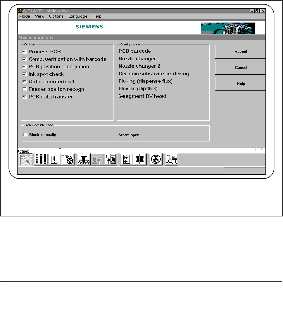
2.4.4.1 Machine Options
Fig. 2.4.5 Machine options
At the "Operator“ operator control level you can select the "Machine options“ menu to identify which machine
options are available and have been activated.
At the "Line engineer“ operator control level you can activate or deactivate the displayed machine options.
Only the machine options that have been configured for the station concerned will be displayed.
PLEASE NOTE
The available machine options and the range of functions are described in Chapter 5 Vision Functions and
Chapter 11 Station Extensions/Options of this User’s Manual.

SIPLACE 80S-20/F4/F4-6/F5 User’s Manual 2 Introduction and Basic Concepts
Edition 03/98 from Software Version SR.404.xx 2.4 Brief Description and Principles of the User Interface
2 - 37
2.4.4.2 Operator Control Level
Three different operator control levels can be allocated:
Operator, Line engineer and Service technician.
Passwords may be allocated for the Line engineer and Service technician operator control levels (see Fig.
2.4.6). Functions that cannot be accessed at a particular operator control level are grayed out and cannot be
selected or used.
Fig. 2.4.6 Operator control level and code word
2 Introduction and Basic Concepts SIPLACE 80S-20/F4/F4-6/F5 User’s Manual
2.4 Brief Description and Principles of the User Interface Edition 03/98 from Software Version SR.404.xx
2 - 38
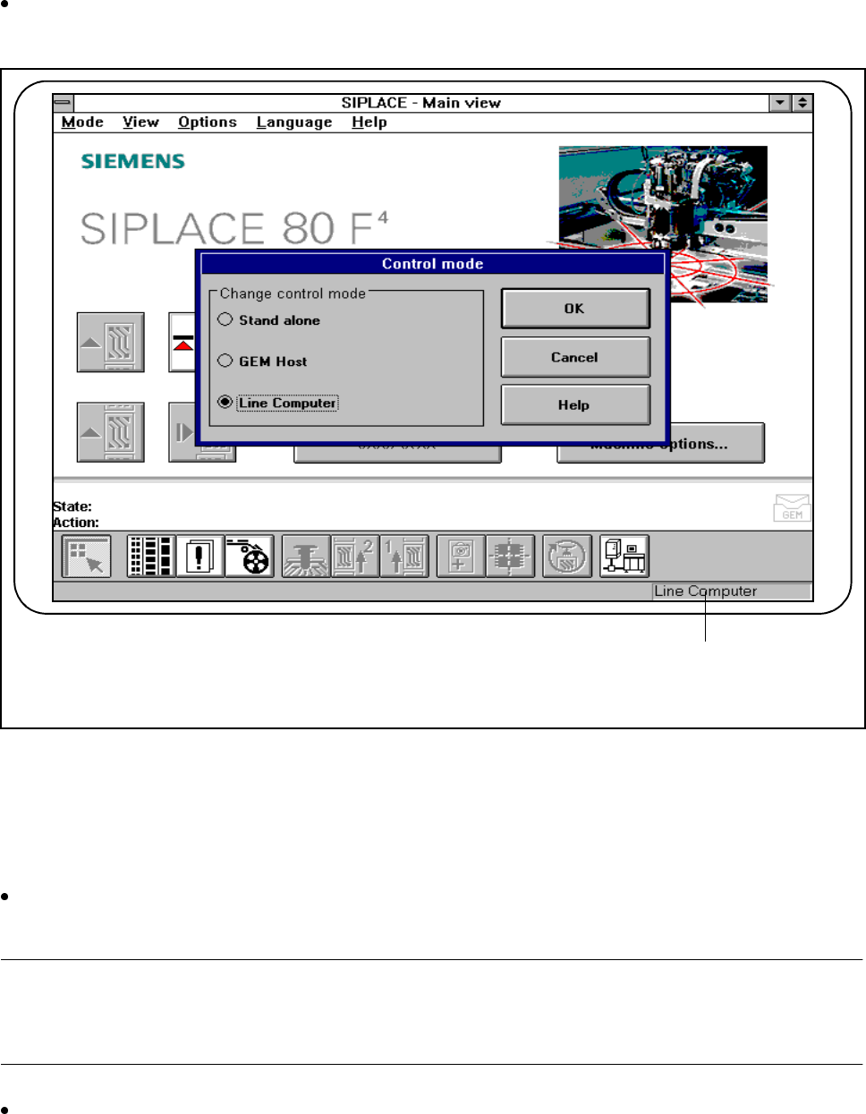
2.4.4.3 Control Mode
The SIPLACE can be supplied with data and operated in three different control modes.
Click on the Control mode option in the Options menu to change the control mode on the station com-
puter.
Fig. 2.4.7 Control mode
- Key to Fig. 2.4.7
1 The control mode currently set is displayed
l With line computer
Select Line computer control mode if cluster data was preset by the line computer. The station computer
will then expect the line computer to specify a cluster.
PLEASE NOTE
Clusters and the set-up should only be specified by the line computer. Stand-alone mode can be used in con-
junction with "New cluster" for testing and service purposes.
Enter the cluster and set-up on the line computer (see the "UNIX line computer" User Manual).
1