80S-2080F480F4-680F5 User’s Manual.pdf - 第21页
SIPLACE 80S-20/F4/F4-6/F5 User’s Manual 0 Introduction Edition 03/98 from S oftware Version SR.404.xx 0.2 Technical Data 0 - 17 0.2.3 Siplace 80F 4 - 6 0.2. 3.1 Gan try Axi s 0.2.3.2 6-nozzle Revolver Head Gantry axis Dr…
0 Introduction SIPLACE 80S-20/F4/F4-6/F5 User’s Manual
0.2 Technical Data Edition 03/98 from Software Version SR.404.xx
0 - 16
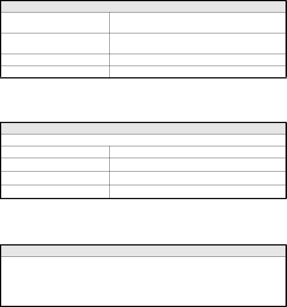
0.2.2.8 Machine control
0.2.2.9 Compressed Air Specification
0.2.2.10 Noise Emission Values
Machine control
Computer machine controller
PC 486
RMOS operating system
Computer station control
Pentium PC
MS-Windows NT 4.0 operating system
Machine control Siemens S5 input/output control
Axis controller Siemens axis controller boards (digital)
Compressed air specification
Max. particle size by density, based on ISO/DIS 8573-1 (Class 1)
Particle size 0.1 µm
Particle density
0.1 mg/m
3
Max. oil content (Class 1)
Particle density 0.01 mg/m
3
Pressure dewpoint (Class 4)
Dewpoint +3
o
Noise emission values specified in accordance with DIN 45 649-1
Emission value at a workstation (L
pAc
) 71 dB (A)
DIN EN ISO 11204 (i)
Sound power level (L
WAc
) 85 dB (A)
E-DIN EN ISO 3744 (i)
001-0307
SIPLACE 80S-20/F4/F4-6/F5 User’s Manual 0 Introduction
Edition 03/98 from Software Version SR.404.xx 0.2 Technical Data
0 - 17
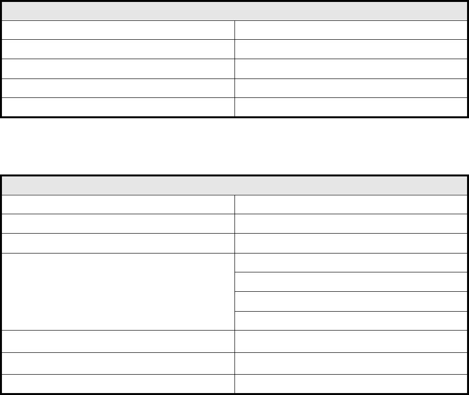
0.2.3 Siplace 80F
4
- 6
0.2.3.1 Gantry Axis
0.2.3.2 6-nozzle Revolver Head
Gantry axis
Drive D.C. servo motors
Path-measuring system Linear incremental scales
Resolution x/y axes 2.5 µm
Speed x axis 2.0 m/s
Speed y axis 2.0 m/s
6-nozzle revolver head
Programmable placement force (z axis) 2.0 N to 5.0 N
Nozzle types 24 (70x, 71x, 72x, 75x, 8xx)
Segments 6
Components that can be assembled
Max. height 6.0 mm
Min. pitch 0.5 mm
Dimensions: 1.5 mm x 0.75 mm to 32 mm x 32 mm
Weight up to 5 grams
Resolution dp turning axes
0.0125
o
Resolution star axis
0.0025
o
Stroke z axis Max. 16 mm
0 Introduction SIPLACE 80S-20/F4/F4-6/F5 User’s Manual
0.2 Technical Data Edition 03/98 from Software Version SR.404.xx
0 - 18
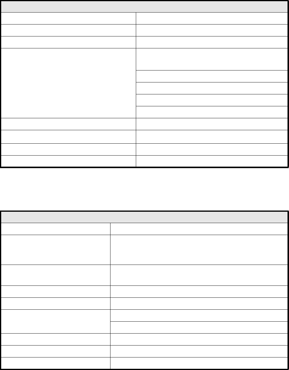
0.2.3.3 IC Placement Head
0.2.3.4 Boards, Components, Tapes
IC placement head
Number 1
Nozzle types 4 (4xx)
Component centering Fine-pitch vision module
Components that can be assembled
Max. height:
PCB
thickness
+ PCB
warpage
+ Comp.
height
≤ 14 mm
Min. pitch 0.4 mm
Min. height 0.3 mm
Dimensions: up to 55 mm x 55 mm (larger on request )
Weight up to 25 grams
Max. component height with motor-driven cutter 10 mm
Resolution of d axis
0.005
o
Stroke z axis Max. 50 mm
Programmable placement force (z axis) 1.0 to 10 N
Boards, components, tapes
Boards (PCB) transport system In-line transport with width adjustment
PCB format 50 mm x 50 mm to 460 mm x 460 mm with PCB buffer
50 mm x 50 mm to 508 mm x 460 mm without PCB buffer
(on request)
Component-free guide edge
of the board
3 mm
Min. PCB thickness 0.5 mm
Max. PCB thickness 4.5 mm
Max. PCB warpage Upwards: 4.5 mm less PCB thickness
Downwards: 0.5 mm plus the PCB thickness
PCB change time 2.5 sec.
Max. number of 8 mm tapes 80
Tape reel diameter Max. 15“ in the reel container