80S-2080F480F4-680F5 User’s Manual.pdf - 第257页
5 Vision Functions SIPLACE 80S-20/F4/F4-6/F5 User’s Manual 5.3 Component Vision System Edition 03/98 from Software Version SR.404.xx 5 - 36 Line engine er Fig. 5.3. 2 Example of irregular compo nents Pitch deviation For …
SIPLACE 80S-20/F4/F4-6/F5 User’s Manual 5 Vision Functions
Edition 03/98 from Software Version SR.404.xx 5.3 Component Vision System
Line engineer 5 - 35
5.3.5 Criteria for Recognition of Components
Shape of the Components
With optical components centering not only regular but also irregular components can be centered. The max-
imum number of leads horizontally and vertically is 99 in each case.
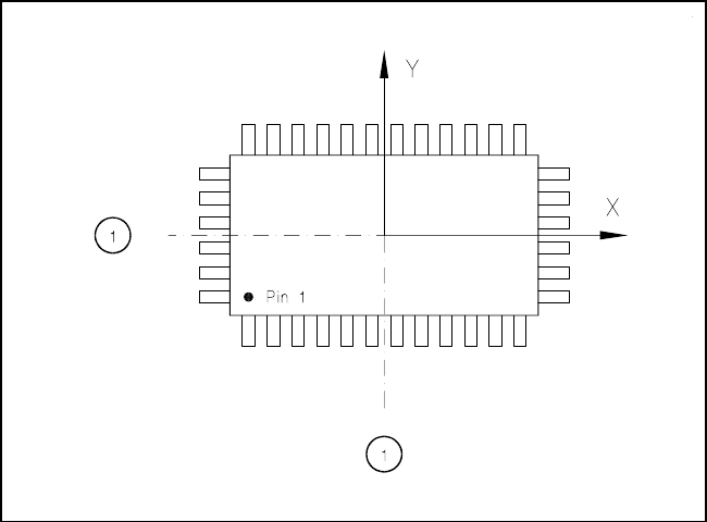
Criteria for regular components
Definition
A component is deemed to be regular when it satisfies the following four conditions:
– rectangular package shapes (special case: square shape)
– only one lead type per side
– only one lead group per side
– opposite lead groups will be located symmetrically with respect to the two main axes
(x and y axes).
Fig. 5.3.1 Regular component
- Key to Fig. 5.3.1
1 Axis of symmetry
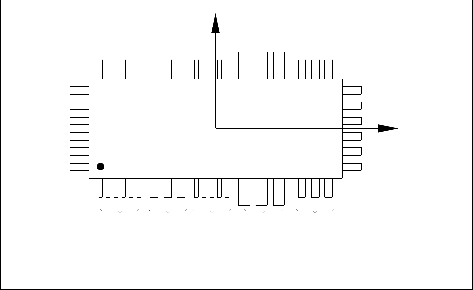
Criteria for irregular components
Definition
A component is deemed to be irregular when it does not satisfy the conditions for regular components.
Additional conditions for centering with the component vision system:
– In any one row up to 3 different lead types are permitted.
– In any one row up to 15 groups are permitted.
5 Vision Functions SIPLACE 80S-20/F4/F4-6/F5 User’s Manual
5.3 Component Vision System Edition 03/98 from Software Version SR.404.xx
5 - 36 Line engineer
Fig. 5.3.2 Example of irregular components
Pitch deviation
For each component the pitch deviation (which is the distance from the center of one lead to the center of the
next) can be edited separately in the GF editor. If this value is exceeded, the component will not be centered
and therefore not inserted.
Limit value for quality measurement
The components must not exceed the limit values for quality measurement as then they would not be
inserted:
– Difference in the number of leads between the original and the model.
– Pitch deviation larger than the value in the GF file.
– Larger orthogonality error than specified in the GF file.
– Larger deviations of the external dimensions.
– Deviation of the central point greater than the permitted positional tolerance for pick-up.
X
Pin 1
Y
X
Pin 1
Type 1 Type 2 Type 1 Type 3 Type 2
Group 1 Group 1 Group 2 Group 1 Group 2
SIPLACE 80S-20/F4/F4-6/F5 User’s Manual 5 Vision Functions
Edition 03/98 from Software Version SR.404.xx 5.3 Component Vision System
Line engineer 5 - 37
5.3.6 Safety Instructions for Component Vision Systems in 80F
4
,
80F
4
-6 or 80F
5
Machines
DANGER
You must not make any modifications whatsoever to or tamper with the safety features of 80F
4
, 80F
4
-6 or
80F
5
machines or the IC or flip-chip modules.
The optical range of the IC and flip-chip camera conforms to laser class 1, provided that the camera is perma-
nently fixed in the automatic placement system and that the protective covers are closed (EN 60825-1 and
IEC 825).
Fig. 5.3.3 Identification label for Laser class 1
s