80S-2080F480F4-680F5 User’s Manual.pdf - 第29页
SIPLACE 80S-20/F4/F4-6/F5 User’s Manual 0 Introduction Edition 03/98 from S oftware Version SR.404.xx 0.3 Installation of the SIPLACE 80 Placement M achine 0 - 25 0.3 Installation of the SIPLACE 80 Placement Machine 0.3.…

0 Introduction SIPLACE 80S-20/F4/F4-6/F5 User’s Manual
0.2 Technical Data Edition 03/98 from Software Version SR.404.xx
0 - 24
0.2.4.8 Permissible Environmental Influences
0.2.4.9 Machine control
0.2.4.10 Compressed Air Specification
0.2.4.11 Noise Emission Values
Permissible environmental influences
Room temperature
Between 15
o
C and 35
o
C
Air humidity
30 to 75 %
(on average not higher than 45%, so that under no circum-
stances will there be condensation in or on the machine)
Machine control
Computer machine controller
PC 486
RMOS operating system
Computer station control
Pentium PC
MS-Windows NT 4.0 operating system
Machine control Siemens S5 input/output control
Axis controller Siemens axis controller boards (digital)
Compressed air specification
Max. particle size by density, based on ISO/DIS 8573-1 (Class 1)
Particle size 0.1 µm
Particle density
0.1 mg/m
3
Max. oil content (Class 1)
Particle density 0.01 mg/m
3
Pressure dewpoint (Class 4)
Dewpoint +3
o
Noise emission values specified in accordance with DIN 45 649-1
Emission value at a workstation (L
pAc
) 71 dB (A)
DIN EN ISO 11204 (i)
Sound power level (L
WAc
) 85 dB (A)
E-DIN EN ISO 3744 (i)
001-0307
SIPLACE 80S-20/F4/F4-6/F5 User’s Manual 0 Introduction
Edition 03/98 from Software Version SR.404.xx 0.3 Installation of the SIPLACE 80 Placement Machine
0 - 25
0.3 Installation of the SIPLACE 80 Placement Machine
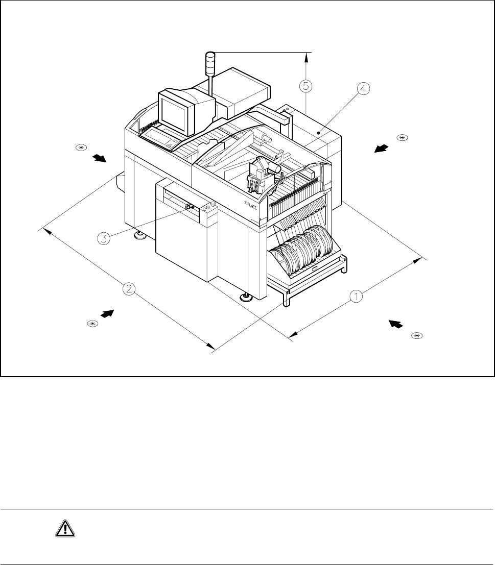
0.3.1 SIPLACE 80 Overview
Fig. 0.3.1 SIPLACE 80S-20 overview
- Key to Fig. 0.3.1
1 Length 2 Width
3 Input conveyor 4 Output conveyor
5 Height incl. warning light
* = Lifting points for the fork lift
CAUTION
When installing, comply with the Technical Data.

0 Introduction SIPLACE 80S-20/F4/F4-6/F5 User’s Manual
0.3 Installation of the SIPLACE 80 Placement Machine Edition 03/98 from Software Version SR.404.xx
0 - 26
0.3.2 Supporting Surface
You must ensure that the machine is set up on a solid non-vibrating floor. If the floor is not level this can be
compensated for using the adjustable feet. The permissible surface load must be at least 1000 kg/m
2
.
0.3.3 Transportation
The machine is shipped from the factory without ancillaries such as keyboard, components tables and screen.
These parts must be fitted or connected before start-up.
A forklift truck or platform truck with a fork length of 2 m must be used for moving and installation.
The lifting points for the forklift truck are indicated in Fig. 0.3.1 by arrows.
0.3.4 Compressed Air Connection
Values are provided in the table in Section 0.2 ’Technical Data’
This is achieved by:
- oil-free compressors, e.g. Atlas Copco model ZR4
- compressed air washer-driers
- series X microfilters, e.g. from Zander
0.3.5 Installation
- The clearance between the individual stations must in each case amount to between 1 and 3 mm at the
PCB conveyors.
- To ensure that the PCBs are conveyed smoothly and without problems the stations should be positioned in
alignment with one another. This can be carried out with the aid of a taut cord or of a shim.
Adjust the feet such that the height of the PCB conveyor belts above floor amounts to 830 mm.
With the aid of a machine spirit level adjust the horizontal position of the station to an accuracy of
0.02 mm/m.
Lock the feet. After locking them, check the position of the machine and if necessary correct it. The feet of
the station must support the station evenly.
CAUTION
Remove all shipping braces from the machine.
Connect up the necessary electrical, mechanical and pneumatic connections in accordance with the Techni-
cal Data (see section 0.2 ’Technical Data’).