80S-2080F480F4-680F5 User’s Manual.pdf - 第310页
SIPLACE 80S-20/F4/F4-6/F5 User’s Manual 5 Vision Functi on s Edition 03/98 from S oftware Version SR.404.xx 5.6 Test Component Line engi neer 5 - 89 With fli p-chips t he balls ar e arranged irregu larly ove r the body o…
5 Vision Functions SIPLACE 80S-20/F4/F4-6/F5 User’s Manual
5.6 Test Component Edition 03/98 from Software Version SR.404.xx
5 - 88 Line engineer
5.6.4.4
Measure Component
Option
NOTE
This option can only be activated if you have already loaded a package form number and a component has
been picked up.
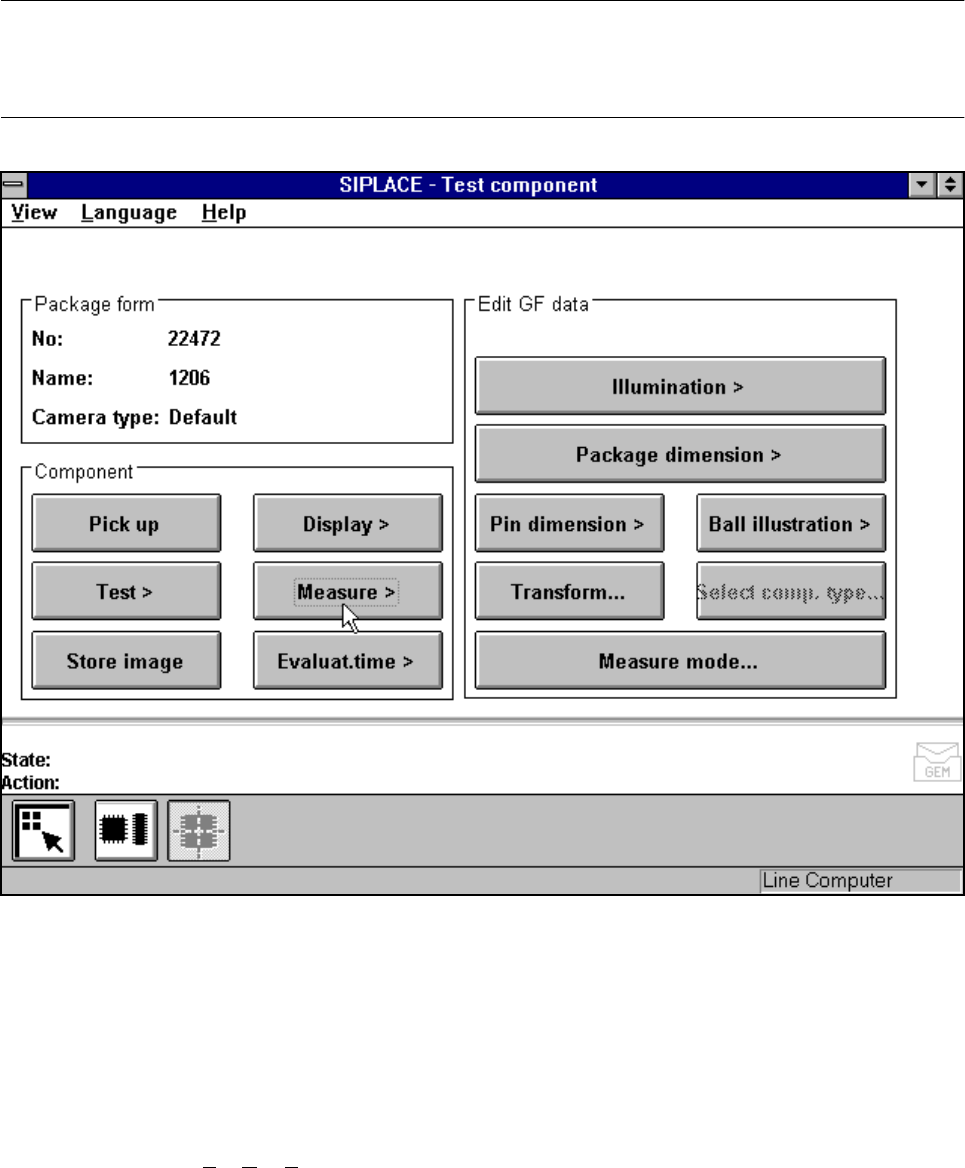
Fig. 5.6.14 Test component menu, Measure component option
When this option is activated the following actions are started:
– The video image appears on the screen.
– The measurement command is given, using the predefined parameters.
– The MVS performs each component-specific measurement step in turn.
– The measurement values are displayed in the video image.
In addition, to conventional components with lead connections the 80F
4
, 80F
4
-6 or 80F
5
machines can also
optically center BGAs (B
all Grid Arrays) and flip-chips. The body of BGA and flip-chip components is made of
passivated silicon chips. Such bodies have strong reflective properties and their surfaces are wavy. The con-
nections of these components take the form of balls with a diameter of at least 80 µm. Ball-grid arrays have
their connections, as the name suggests, arranged in the form of a grid - this means that they can be
described in terms of rows and columns.
SIPLACE 80S-20/F4/F4-6/F5 User’s Manual 5 Vision Functions
Edition 03/98 from Software Version SR.404.xx 5.6 Test Component
Line engineer 5 - 89
With flip-chips the balls are arranged irregularly over the body of the component body. The coordinates of
each connection will therefore need to be ascertained individually.
The IC head of the 80F
4
, 80F
4
-6 or 80F
5
machine picks up the BGAs or flip-chips from flatpack magazines.
However the evaluation procedures used to date for conventional components are no longer adequate for the
optical centering of BGAs or flip-chips. For this reason new evaluation methods and new lighting techniques
have been developed for the IC sensor and FC sensor in order that this new generation of components can
be centered. BGAs and flip-chips which cannot be centered optically will be returned to the flatpack maga-
zines by the IC head.
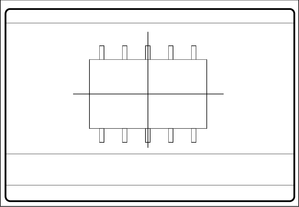
Fig. 5.6.15 Test component menu, Measure component video image
Optical surveying of conventional components with lead connections with the 80S-20 and 80F
4
/F
4
-6/F
5
place-
ment machines:
The crosshairs indicate the component’s center. The component outlines are emphasized in color.
The measured values represent the geometric component parameters such as
– Lead skew
The value for lead skew will be indicated if you have selected the lead-driven measurement mode.
– Pitch
The value for pitch will be indicated if the corner-driven measurement mode is active as the last measure-
ment step.
– Number of leads
– x / y offset
Measure component GF No. = 5
X offset = ... Y offset = ... Phi = ...
Orthogon = ...
No. of pins = ...
Quality fact. = ...
Length[mm] = ...
Width[mm] = ...
Spacing[mm] =
RET: Measure component
P.dev.[mm] =
5 Vision Functions SIPLACE 80S-20/F4/F4-6/F5 User’s Manual
5.6 Test Component Edition 03/98 from Software Version SR.404.xx
5 - 90 Line engineer
– Orthogonality
– Dimensions of the component
– Skew and
– Factor for the quality of measurement.
Use Esc to quit this option. The video image disappears and the Test component menu is displayed once
more on the screen.
Color overlays of the individual measurement steps during step mode
1. Size-driven mode
See Section 5.6.4.14 from Page 5 - 109 for a definition of the measuring methods.
You can recognize this measurement method by rotating windows around the component edges
Procedure:
I. Inside the search window profiles are created in the x and y directions. With the aid of the gradients thus
formed and a geometric filter the approximate position of the component is determined.
II. Windows rotate around the component’s edges. The profile and gradients are determined for each win-
dow. The sum of the gradients is an indication of the agreement of the window angle with the position of
the component.
If the sum of the gradients reaches a maximum the angular position of the component has been deter-
mined.
III. Under the angle determined in step II the first step (I) is repeated. Now it will be possible to determine the
position of the component in the x and y directions more accurately.
Rectangles:
green: x and y pick-up tolerances
orange: component dimensions and tolerances supplied by the station
blue: search area for position recognition
Comments
1. The position of the component as determined must be within the green rectangle otherwise the
component will not be placed.
Applies to all measurement steps!
2. The component must be located within the orange window otherwise the measurement results will
not dependable.
3. The search areas should have the same alignment as the component and also be larger than the
component.
Lines:
red: Edges of the component detected
Comments:
The red lines may often be covered by others and thus possible not detectable.