80S-2080F480F4-680F5 User’s Manual.pdf - 第323页
5 Vision Functions SIPLACE 80S-20/F4/F4-6/F5 User’s Manual 5.6 Test Component Edition 03/98 from Software Version SR.404.xx 5 - 102 Line engine er 5.6. 4.9 Package Dimension Option Here you have the p ossibility of chang…
SIPLACE 80S-20/F4/F4-6/F5 User’s Manual 5 Vision Functions
Edition 03/98 from Software Version SR.404.xx 5.6 Test Component
Line engineer 5 - 101
5.6.4.8
Illumination
Option
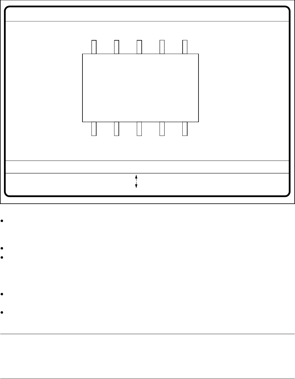
When this option is selected the video image for checking and setting illumination will appear.
Fig. 5.6.20 Test component menu, Illumination video image
You can use the arrow keys to increase or decrease the brightness of the rows of LEDs in the component
camera system which illuminate the component. The brightness can be set within a range of 256 steps
with 255 being the maximum value.
Use the spacebar to toggle the step size for changing the brightness from 1 to 10 µm and back.
Use the tab key to move between the four illumination levels: steep (top row of LEDs), medium (second
row of LEDs), flat (third row of LEDs) and X plane camera lighting (bottom row of LEDs). The X plane illu-
mination level is used to optically center flip-chip components on the 6-nozzle revolver head with the illumi-
nation system for flip-chips, bare dies and standard components.
Press the Return key to execute the individual measurement steps which are included in the measure-
ment conditions.
With Esc you can quit the option. You will then be returned to the Test component menu.
NOTE
Section 5.7.6 ’Setting the Components Illumination at the 12x Revolver Head Camera’, Page 128, and Sec-
tion 5.7.7 ’Setting the Components Illumination at the IC Head Camera’, Page 135, contain instructions for
selecting the illumination parameters.
GF No. = 5Illumination
RET: Test component
Illuminat. = X plane/flat/middle/steep Field step =
Blank: step width
Tab: Illumination
Brightness = 0 ... 255
: Brightness up
: Brightness down
5 Vision Functions SIPLACE 80S-20/F4/F4-6/F5 User’s Manual
5.6 Test Component Edition 03/98 from Software Version SR.404.xx
5 - 102 Line engineer
5.6.4.9
Package Dimension
Option
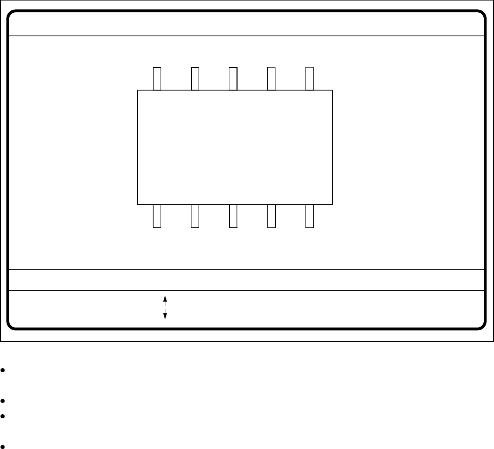
Here you have the possibility of changing the optical package width and length should the imaging reduction
effect be too marked. This effect occurs mainly with cylindrical components and with PLCCs.
Fig. 5.6.21 Test component menu, Package dimension video image
With the arrow keys you can change the length and width of the component. The current geometric data
will be displayed.
Use the spacebar to select different sides of the component.
With the Return key you can trigger the individual measurement steps which are specified in the measure-
ment conditions.
Press Esc to quit the option.
GF No. = 5
: larger
: smaller
RET: Test component
Blank: Pack. side
Pack. side = opt. l.[mm] = ... opt. w.[mm] = ...
Pin dimension
SIPLACE 80S-20/F4/F4-6/F5 User’s Manual 5 Vision Functions
Edition 03/98 from Software Version SR.404.xx 5.6 Test Component
Line engineer 5 - 103
5.6.4.10
Pin Dimension
Option
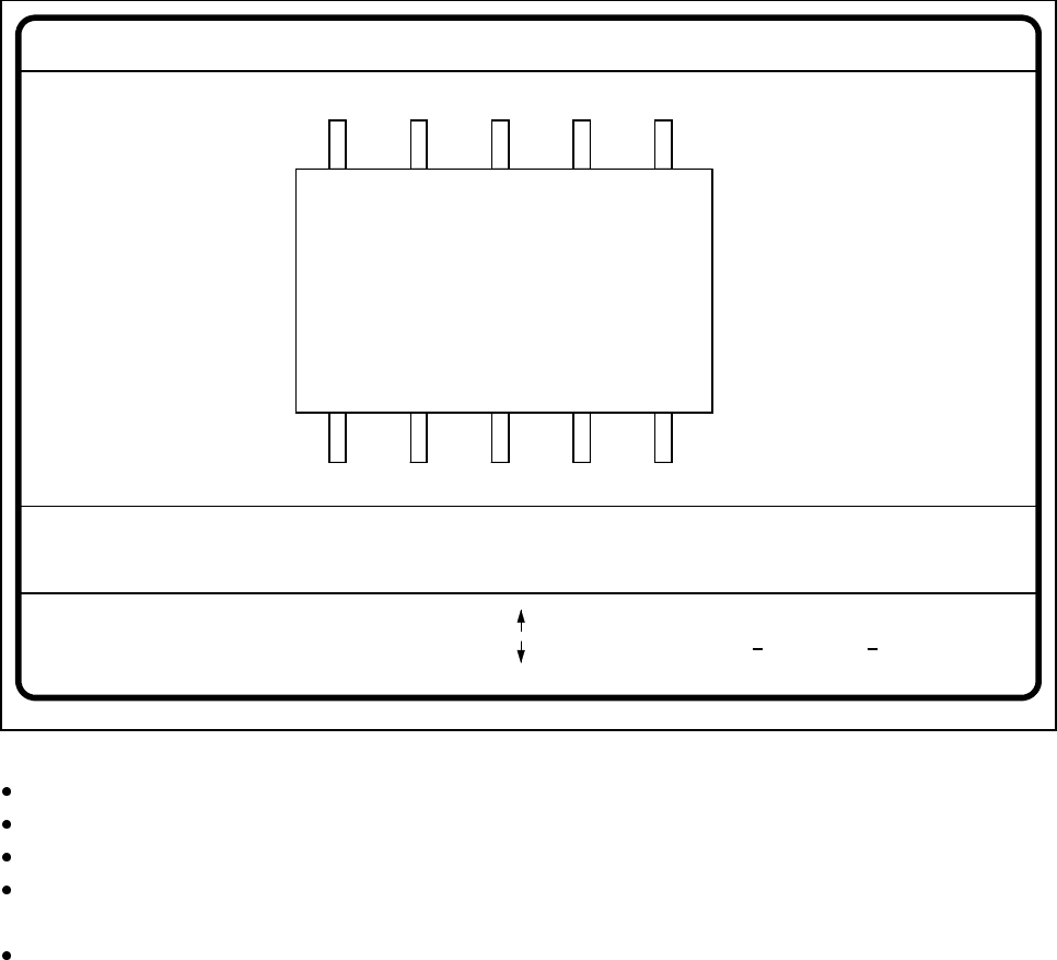
With this option you can change the optical pin width and length. In addition, you can also change the pin con-
trast if imaging reduction results in the pins not being dependably recognized.
Fig. 5.6.22 Test component menu, Pin dimension option
Use the tabulator key to select the pin model.
With the spacebar select the side of the pin.
Use the + and - keys to raise or lower the pin contrast.
The arrow keys are used for changing the pin width and length. The component will appear as a silhouette
on the screen together with the updated geometric pin data.
With the Return key you can trigger the individual measurement steps which are specified in the measure-
ment conditions for the specified component.
Press Esc to cancel the option, even if not all measurement steps have been carried out. You will then be
returned to the Test component menu.
GF No. = 5Pin dimension
+ : contrast +
opt. l. [mm] = ...
opt. w. [mm] = ...
Pin side =
Pin definition = 1..n
RET: Test component
Tab: Pin model
Blank: Pin side
Pin contrast =
: larger
: smaller
: contrast