80S-2080F480F4-680F5 User’s Manual.pdf - 第324页
SIPLACE 80S-20/F4/F4-6/F5 User’s Manual 5 Vision Functi on s Edition 03/98 from S oftware Version SR.404.xx 5.6 Test Component Line engi neer 5 - 103 5.6. 4.10 Pin Dimension Option With this option you ca n chang e the o…
5 Vision Functions SIPLACE 80S-20/F4/F4-6/F5 User’s Manual
5.6 Test Component Edition 03/98 from Software Version SR.404.xx
5 - 102 Line engineer
5.6.4.9
Package Dimension
Option
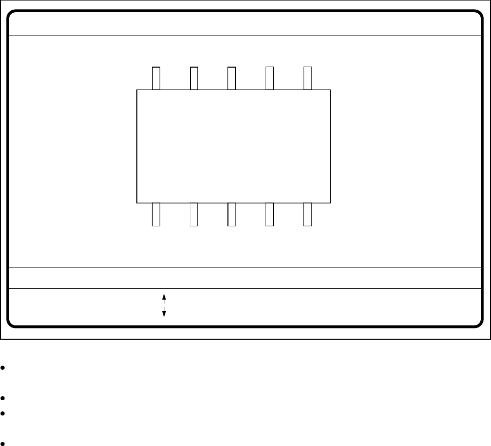
Here you have the possibility of changing the optical package width and length should the imaging reduction
effect be too marked. This effect occurs mainly with cylindrical components and with PLCCs.
Fig. 5.6.21 Test component menu, Package dimension video image
With the arrow keys you can change the length and width of the component. The current geometric data
will be displayed.
Use the spacebar to select different sides of the component.
With the Return key you can trigger the individual measurement steps which are specified in the measure-
ment conditions.
Press Esc to quit the option.
GF No. = 5
: larger
: smaller
RET: Test component
Blank: Pack. side
Pack. side = opt. l.[mm] = ... opt. w.[mm] = ...
Pin dimension
SIPLACE 80S-20/F4/F4-6/F5 User’s Manual 5 Vision Functions
Edition 03/98 from Software Version SR.404.xx 5.6 Test Component
Line engineer 5 - 103
5.6.4.10
Pin Dimension
Option
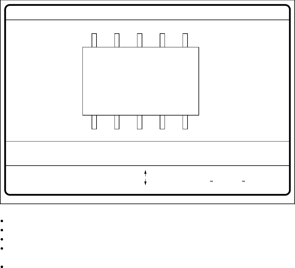
With this option you can change the optical pin width and length. In addition, you can also change the pin con-
trast if imaging reduction results in the pins not being dependably recognized.
Fig. 5.6.22 Test component menu, Pin dimension option
Use the tabulator key to select the pin model.
With the spacebar select the side of the pin.
Use the + and - keys to raise or lower the pin contrast.
The arrow keys are used for changing the pin width and length. The component will appear as a silhouette
on the screen together with the updated geometric pin data.
With the Return key you can trigger the individual measurement steps which are specified in the measure-
ment conditions for the specified component.
Press Esc to cancel the option, even if not all measurement steps have been carried out. You will then be
returned to the Test component menu.
GF No. = 5Pin dimension
+ : contrast +
opt. l. [mm] = ...
opt. w. [mm] = ...
Pin side =
Pin definition = 1..n
RET: Test component
Tab: Pin model
Blank: Pin side
Pin contrast =
: larger
: smaller
: contrast
5 Vision Functions SIPLACE 80S-20/F4/F4-6/F5 User’s Manual
5.6 Test Component Edition 03/98 from Software Version SR.404.xx
5 - 104 Line engineer
5.6.4.11
Ball Illustration
Option
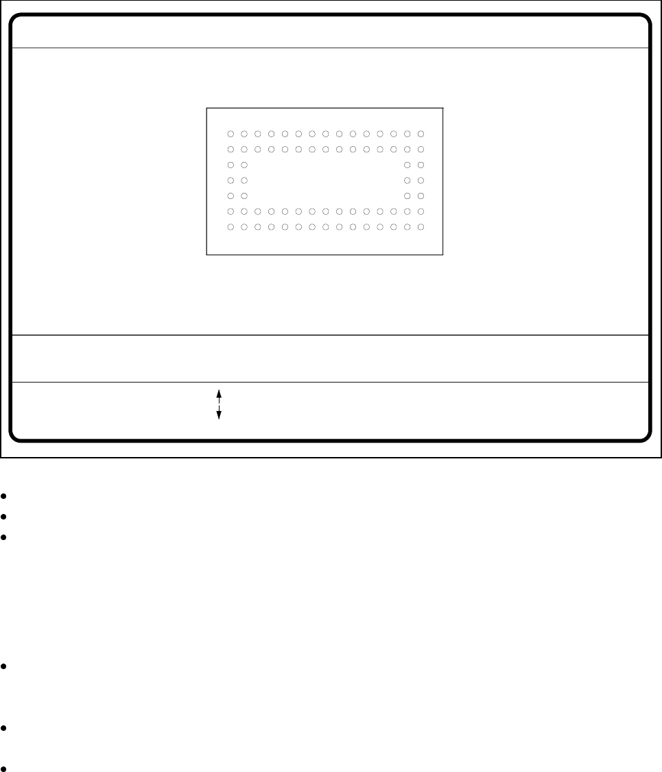
With this option you can change the ball model description.
Fig. 5.6.23 Test component menu, Ball image video image
Use the tabulator key to select the ball model.
With the spacebar select the radius type - inner or outer radius.
Use the arrow keys to enlarge or reduce the internal or external radius of the ball. The balls will be dis-
played in their geometric dimensions as a pixel image on the lefthand edge of the video image.
The value of the inner radius the ball shape:
– If the inner radius is equal to 0, the ball will take the form of a circle.
– If the inner radius is greater than 0, the ball will take the form of a doughnut.
Use the + or - keys to increase or reduce the ball contrast.
Select ball contrast > 0, if the ball is lighter than the background.
Select ball contrast < 0, if the ball is darker than the background.
With the Return key you can trigger the individual measurement steps which are specified in the measure-
ment conditions for the specified component.
Press Esc to cancel the option, even if not all measurement steps have been carried out. You will then be
returned to the Test component menu.
GF no. = 5Ball image
RET: Test comp.
Tab: Ball model
Rad. i.[mm]
Ball model = 1
Rad. e.[mm]
Rad. type: intern./extern.
= 0.500
= 1.500
+ : Contrast +
- : Contrast -
Contrast a.
Contrast i.
= 10
= 20
: larger
: smaller
Blank: Radius type