80S-2080F480F4-680F5 User’s Manual.pdf - 第328页
SIPLACE 80S-20/F4/F4-6/F5 User’s Manual 5 Vision Functi on s Edition 03/98 from S oftware Version SR.404.xx 5.6 Test Component Line engi neer 5 - 107 This option a llows you t o – sele ct and ac tivate a p articular meas…

5 Vision Functions SIPLACE 80S-20/F4/F4-6/F5 User’s Manual
5.6 Test Component Edition 03/98 from Software Version SR.404.xx
5 - 106 Line engineer
Buttons
– Accept
Click on the Accept button to save the settings. The option box will then close.
– Cancel
With Cancel you can discard the settings. The option box will then close.
– Help
With the Help button you can access explanatory material regarding the on-screen presentation.
– Number input field
You can choose the number of sections
by entering the numerical value directly into the display field, or
by moving the scroll field in the scroll bar to the right or left using the mouse. In this way you can run
back and forth through the values range (1 - 5), or
by clicking on the lefthand or right-hand arrow on the scroll bar. In this way you can increase or
decrease the number of selections.
Programming the transformation table
– Specifying the output values
Position the mouse pointer over the ends of the transformation lines of each section. The ends are marked
with small horizontal lines. A vertical double arrow will then appear on the screen. Click on the lefthand
mouse key and move the arrow upwards or downwards. This will move the selected end of the transforma-
tion line and the numerical value will be displayed at OUT Begin or OUT End.
– Selecting the section limits
The graphical representation in Fig. 5.6.24, Page 5 - 105 shows equidistant section limits with the ranges
0 - 50, 51 - 100 and so on. You can change these section limits if you wish. However limits 0 and 255 are
permanently allocated and cannot therefore be moved.
Position the mouse pointer on a section limit (but not 0 and 255). A horizontal double arrow will appear on
the screen. Hold down the lefthand mouse pointer and use it to drag the section limit in the direction you
want. The corresponding numerical value will be displayed at IN:.
– Once you have programmed your transformation table you can quit the option box by clicking on Accept
or Cancel.
5.6.4.13
Measure Mode
Option
NOTE
This option can only be activated when a GF number has been loaded.
The sensor-specific part of the package form includes a data structure with measurement conditions for the
components. In this menu you can manipulate these measurement conditions. The menu options are prima-
rily intended for the creation of your own user-specified GF file.

SIPLACE 80S-20/F4/F4-6/F5 User’s Manual 5 Vision Functions
Edition 03/98 from Software Version SR.404.xx 5.6 Test Component
Line engineer 5 - 107
This option allows you to
– select and activate a particular measurement method or combination of several measurement methods
– deactivate individual measurement methods, and
– change the hex parameters belonging to each measurement method.
The hex parameters for the individual measuring methods can be modified in two ways:
– either indirectly, i.e. menu-driven
You will be guided by the package form manipulator by means of setting menus and explanatory text in
order to obtain the desired measuring results quickly and accurately.
– or directly, i.e. you enter the necessary hex parameters directly into the ’Measuring mode 2’ input box.
NOTE
Please note that entering the hex values directly requires considerable knowledge of the measuring
method sequence.
If you intend to enter or modify hex values directly, please contact Siemens Service first and do not enter
the bit-coded hex values until you have spoken to the Service Department.
We recommend that you generally use the menu-driven package form manipulator.
5 Vision Functions SIPLACE 80S-20/F4/F4-6/F5 User’s Manual
5.6 Test Component Edition 03/98 from Software Version SR.404.xx
5 - 108 Line engineer
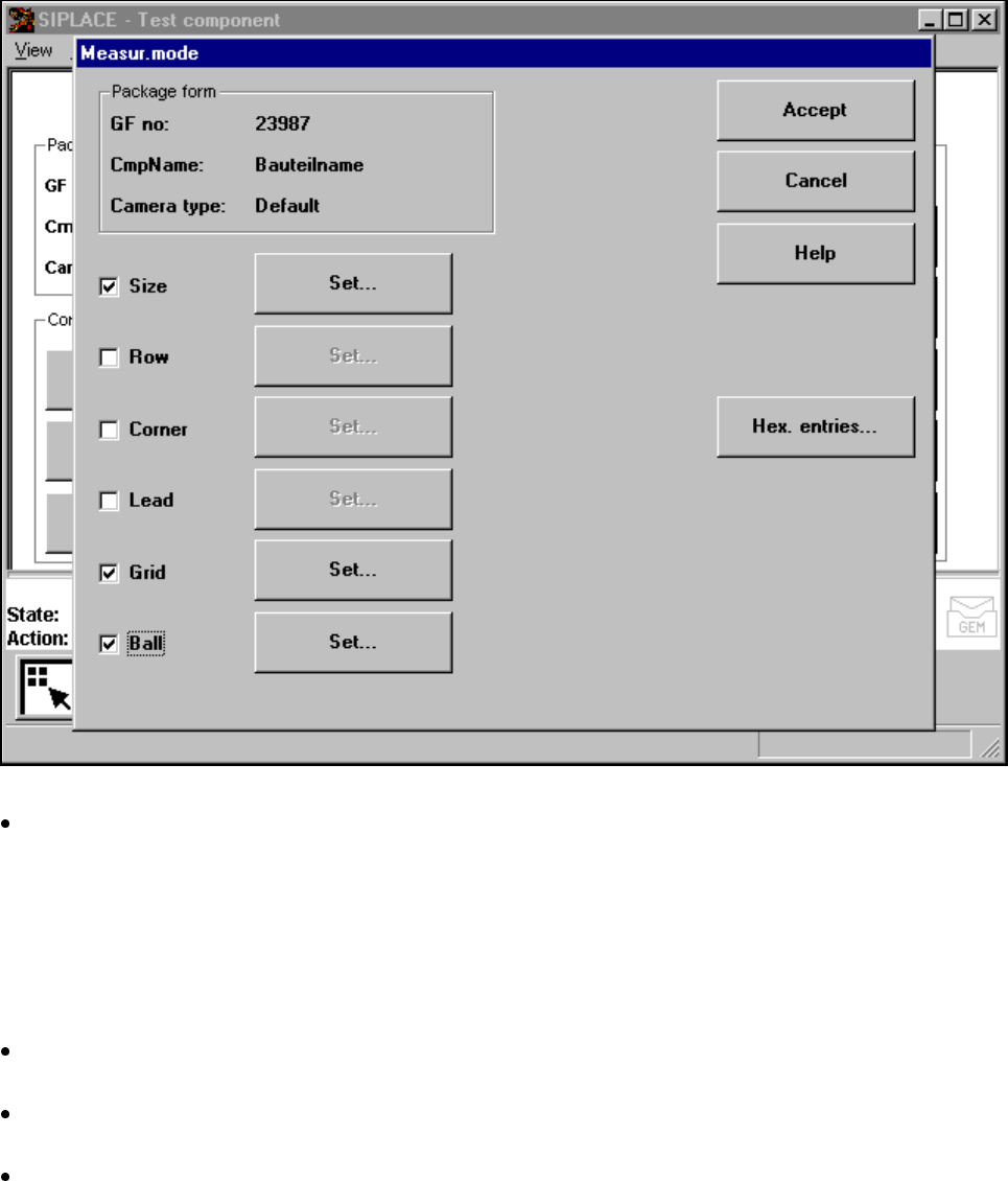
Measuring mode menu
Click on the ’Measuring mode’ field to call up the Measuring mode menu.
Fig. 5.6.25 Test component menu, Measur. mode option
In the left column of the box, the desired measuring method can be activated or deactivated by clicking
with the mouse. A cross indicates that you have activated the measuring method. The ‘Setting' field for
calling up the sub-menu changes from grey to black.
Please note that
– there is currently no option for setting the ’Ball’ measuring mode.
– You can only use measuring modes that have been activated.
Use the ‘Hex input’ field to call up the ‘Measuring mode 2’ input menu for directly entering hex values.
Please follow the instructions on Page 107.
Select ‘Accept’ to close the ‘Measuring mode’ menu. The modified measuring conditions will be entered
into the package form file on the station computer.
Select ‘Abort’ to interrupt the operation without transferring the data and to return to the ‘Test component’
menu.