80S-2080F480F4-680F5 User’s Manual.pdf - 第331页
5 Vision Functions SIPLACE 80S-20/F4/F4-6/F5 User’s Manual 5.6 Test Component Edition 03/98 from Software Version SR.404.xx 5 - 110 Line engine er Grid-d riven (component inspection with the 80F 4 , 80F 4 -6 o r 80 F 5 m…

SIPLACE 80S-20/F4/F4-6/F5 User’s Manual 5 Vision Functions
Edition 03/98 from Software Version SR.404.xx 5.6 Test Component
Line engineer 5 - 109
5.6.4.14 Information on Measurement Methods
As far as conventional components with lead connections are concerned, component centering is essentially
based on four measurement methods used to determine the position (x and y coordinates, Φ = skew) of the
component and the lead parameters:
– Size-driven mode
– Row-driven mode
– Corner-driven mode
– Lead-driven mode
For BGAs (B
all Grid Arrays) and flip-chips new algorithms have been implemented in order to determine the
position (x and y coordinates, Φ = skew) of the component and the ball parameters (see ’Measure Compo-
nent Option’ on Page 5 - 88.):
– Grid-driven mode
– Ball-driven mode
In accordance with your specifications any measurement method can be omitted from this sequence. How-
ever, it is not possible to change the way this sequence runs.
Definition of the measuring methods
Size-driven
This measurement method has been especially developed for small components. On the basis of the infor-
mation on dimension parameters the position and rotation of small components is determined rapidly and
reliably.
This method is very resistant to unwanted intrusive elements such as ink markings.
The size-driven mode also employs profiling. You can have the profile formed along either the width
or
the
length of the component. You should make your choice within the options field. The default selection is for
profiling along the longer side.
Row-driven
This measurement method is based on information from one row of leads.
This method is very fast and supplies approximate values for the coordinates and rotational angle of the
component.
Corner-driven (Component inspection)
The measurement results provide precise information on the coordinates and rotation of the component,
the number of leads, the pitch and the row offset.
This method is not sensitive to fluctuations in the lead dimensions.
Lead-driven (Leads inspection)
This method is used to obtain information from an inspection of every single lead.
The following combinations of measurement methods are used:
– Size-driven — corner-driven — lead-driven (see the table in Section 5.6.4.15) or
– Row-driven — corner-driven — lead-driven (see the table in Section 5.6.4.15)
5 Vision Functions SIPLACE 80S-20/F4/F4-6/F5 User’s Manual
5.6 Test Component Edition 03/98 from Software Version SR.404.xx
5 - 110 Line engineer
Grid-driven (component inspection with the 80F
4
, 80F
4
-6 or 80F
5
machines)
The measurement results will provide information on the approximate coordinates and approximate rota-
tion of the component. In addition, you will be informed of the quality of measurement.
Ball-driven (determining the balls position with the 80F
4
, 80F
4
-6 or 80F
5
machines)
The measurement results will provide precise information on the approximate coordinates and approxi-
mate rotation of the component. In addition, you will be informed of the maximum ball offset and the quality
of measurement.
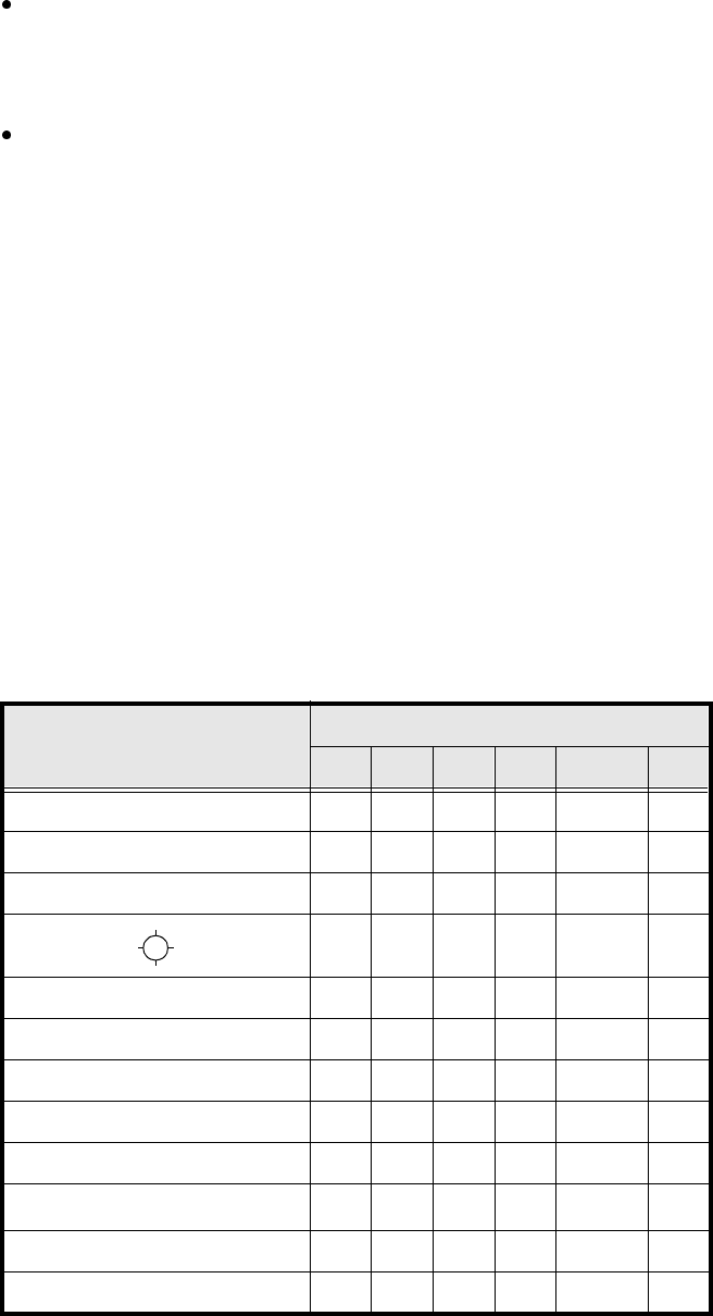
5.6.4.15 Recommendations regarding the Optimum Sequence of Measurement
Methods
The following table contains our recommendations for the optimum sequence of measurement methods for
particular components. The following abbreviations are used:
B = ball-driven
C = corner-driven
G = grid-driven
L = lead-driven
R = row-driven
S = size-driven
*)
L applies to irregularly shaped components with separate windows
Component Measurement sequence
S R G C L B
MELF S L
CHIP S L
SOT S C L
SL
SOJC6 S C
SOJC14 R C
LCC R C L
PLCC R C L
QFP R C L
TAB R C
L
*)
BGA, Flip-Chip S G B
Bare Dies S
Tab. 5.6.1 Optimum sequences of measurement methods
SIPLACE 80S-20/F4/F4-6/F5 User’s Manual 5 Vision Functions
Edition 03/98 from Software Version SR.404.xx 5.6 Test Component
Line engineer 5 - 111
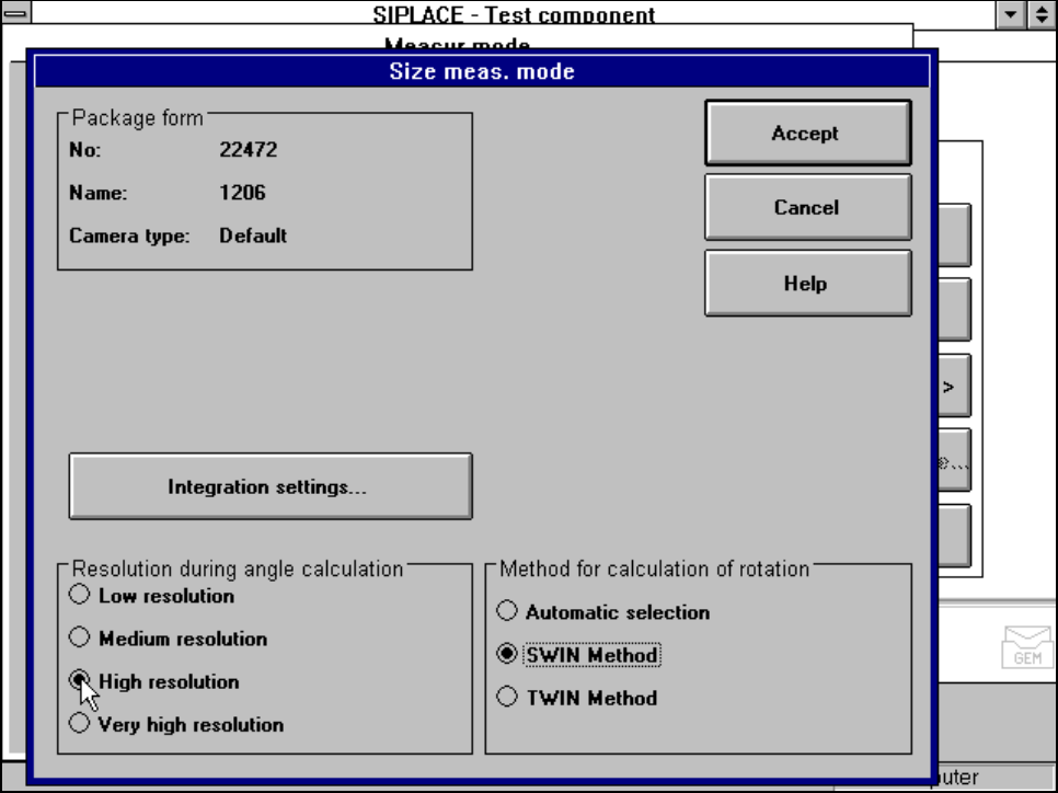
5.6.4.16 ‘Size’ measuring mode
Click on the ‘Setting’ field for the ‘Size’ measuring mode to overlay the Size measuring mode menu on the
screen.
Fig. 5.6.26 Measuring mode option, Size measuring mode menu
This menu is used to
– vary the resolution the angle calculation.
– specify the method for the rotation calculation and
– vary the integration settings.
Resolution for the angle calculation
In this measuring mode, if the component rotation has been calculated incorrectly on account of ambiguity,
you can increase the angular resolution in order to determine the angle of rotation. The following increments
may be used in relation to the resolution in order to determine the angle of the components:
– Low resolution: