80S-2080F480F4-680F5 User’s Manual.pdf - 第332页
SIPLACE 80S-20/F4/F4-6/F5 User’s Manual 5 Vision Functi on s Edition 03/98 from S oftware Version SR.404.xx 5.6 Test Component Line engi neer 5 - 111 5.6. 4.16 ‘Size’ measuring mode Click o n the ‘Se tting’ field for the…
5 Vision Functions SIPLACE 80S-20/F4/F4-6/F5 User’s Manual
5.6 Test Component Edition 03/98 from Software Version SR.404.xx
5 - 110 Line engineer
Grid-driven (component inspection with the 80F
4
, 80F
4
-6 or 80F
5
machines)
The measurement results will provide information on the approximate coordinates and approximate rota-
tion of the component. In addition, you will be informed of the quality of measurement.
Ball-driven (determining the balls position with the 80F
4
, 80F
4
-6 or 80F
5
machines)
The measurement results will provide precise information on the approximate coordinates and approxi-
mate rotation of the component. In addition, you will be informed of the maximum ball offset and the quality
of measurement.
5.6.4.15 Recommendations regarding the Optimum Sequence of Measurement
Methods
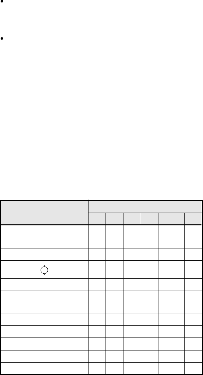
The following table contains our recommendations for the optimum sequence of measurement methods for
particular components. The following abbreviations are used:
B = ball-driven
C = corner-driven
G = grid-driven
L = lead-driven
R = row-driven
S = size-driven
*)
L applies to irregularly shaped components with separate windows
Component Measurement sequence
S R G C L B
MELF S L
CHIP S L
SOT S C L
SL
SOJC6 S C
SOJC14 R C
LCC R C L
PLCC R C L
QFP R C L
TAB R C
L
*)
BGA, Flip-Chip S G B
Bare Dies S
Tab. 5.6.1 Optimum sequences of measurement methods
SIPLACE 80S-20/F4/F4-6/F5 User’s Manual 5 Vision Functions
Edition 03/98 from Software Version SR.404.xx 5.6 Test Component
Line engineer 5 - 111
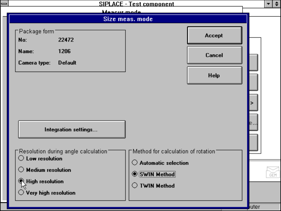
5.6.4.16 ‘Size’ measuring mode
Click on the ‘Setting’ field for the ‘Size’ measuring mode to overlay the Size measuring mode menu on the
screen.
Fig. 5.6.26 Measuring mode option, Size measuring mode menu
This menu is used to
– vary the resolution the angle calculation.
– specify the method for the rotation calculation and
– vary the integration settings.
Resolution for the angle calculation
In this measuring mode, if the component rotation has been calculated incorrectly on account of ambiguity,
you can increase the angular resolution in order to determine the angle of rotation. The following increments
may be used in relation to the resolution in order to determine the angle of the components:
– Low resolution:
5 Vision Functions SIPLACE 80S-20/F4/F4-6/F5 User’s Manual
5.6 Test Component Edition 03/98 from Software Version SR.404.xx
5 - 112 Line engineer
– Medium resolution
Determining the angle every 4° within the angular tolerance
– High resolution
Determining the angle every 2° within the angular tolerance
– Very high resolution
Determining the angle every 1° within the angular tolerance
Method for calculating the rotation
Here you must specify the number of rotation windows in order to determine the angle:
– Automatic selection
The system selects the number of windows.
– SWIN method (Single Window)
Selects a single window. This method is suitable for small components and fluctuating dimensions.
– TWIN method (Two Windows)
Two windows are selected. This method is particularly suitable for rapid analysis, for PLCCs, for example.
However, this requires the structures to be investigated to lie in the center of the window. If this is not the
case, select just one window (SWIN method).
Integration settings
If you click on the ’Integration settings’ field, the Integration settings of Size measuring mode menu will
appear on screen.
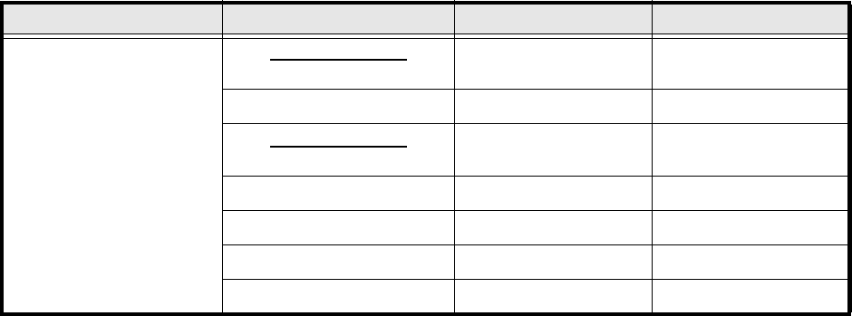
Angular tolerance 0° - 15° 16° - 25° 26° - 45°
Determining the
angle for the
following
angles
- Angular tolerance
2
- 15° - 33°
0° - 8° - 18°
+Angular tolerance
2
0° - 8°
8° 0°
15° 8°
18°
33°
Tab. 5.6.2 Resolution for the angle calculation: Low resolution