80S-2080F480F4-680F5 User’s Manual.pdf - 第352页
SIPLACE 80S-20/F4/F4-6/F5 User’s Manual 5 Vision Functi on s Edition 03/98 from S oftware Version SR.404.xx 5.7 Guidelines for Describing Package Form s Line engi neer 5 - 131 Fig. 5.7.7 Illumination parameters for s tan…
5 Vision Functions SIPLACE 80S-20/F4/F4-6/F5 User’s Manual
5.7 Guidelines for Describing Package Forms Edition 03/98 from Software Version SR.404.xx
5 - 130 Line engineer
5.7.6.2 Pseudo color representation
The pseudo color representation provides a powerful and objective assessment of the illumination, by repre-
senting a brightness value in a color.
A contrast of at least 4 color scales between the lead and body is required for a measurement. In the ‘Illumina-
tion’ menu of the package form manipulator, components are displayed in the pseudo color representation on
the station computer monitor.
5.7.6.3 Settings for Illuminating Standard Components
The standard range of components includes chips (0402 to 2220), tantalum capacitors, Melf components,
PLCCs, QFPs, SOs, SOJs, TSOPs, ICs, power components, flip-chips, µBGAs and BGAs.
For the components which are listed below the GF interpreter in the station computer uses the default illumi-
nation parameters listed in Fig. 5.7.7:
– Chips (0402 to 2220)
– Tantalum capacitors (component bodies, non-reflective)
– Melf
– PLCC, QFP, SO, SOJ, TSOP, ICs, power ICs
– Flip-chips, µBGAs, BGAs (not ceramic BGAs)
As a rule you will not need to change the illumination parameters for the standard components. For all other
components you will need to determine the illumination values and test them (see Section 5.7.6.4, Page 5 -
131).
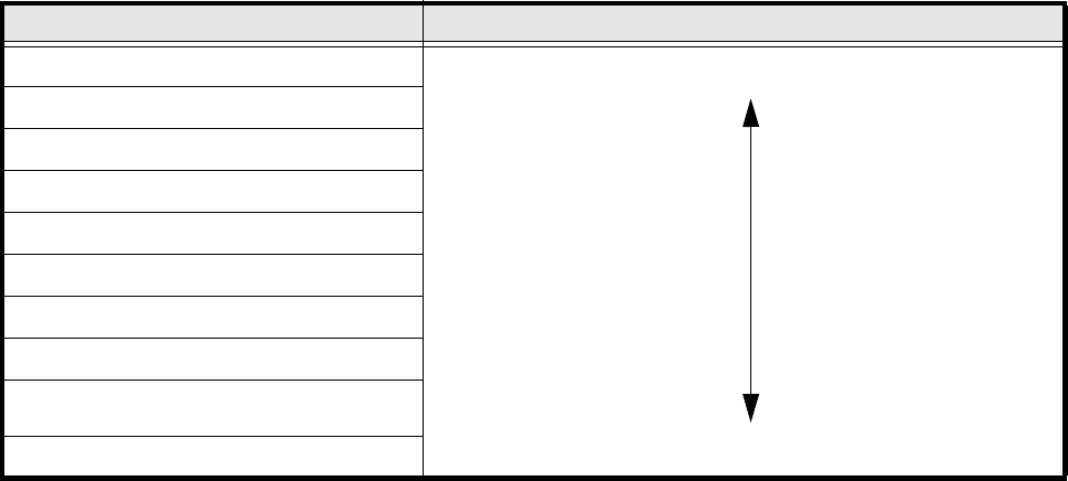
Color scale Brightness
white light
yellow
orange
red
brown
green
light blue
blue
violet
black dark
Tab. 5.7.3 Conversion table for the pseudo color representation at the 12x revolver head
SIPLACE 80S-20/F4/F4-6/F5 User’s Manual 5 Vision Functions
Edition 03/98 from Software Version SR.404.xx 5.7 Guidelines for Describing Package Forms
Line engineer 5 - 131
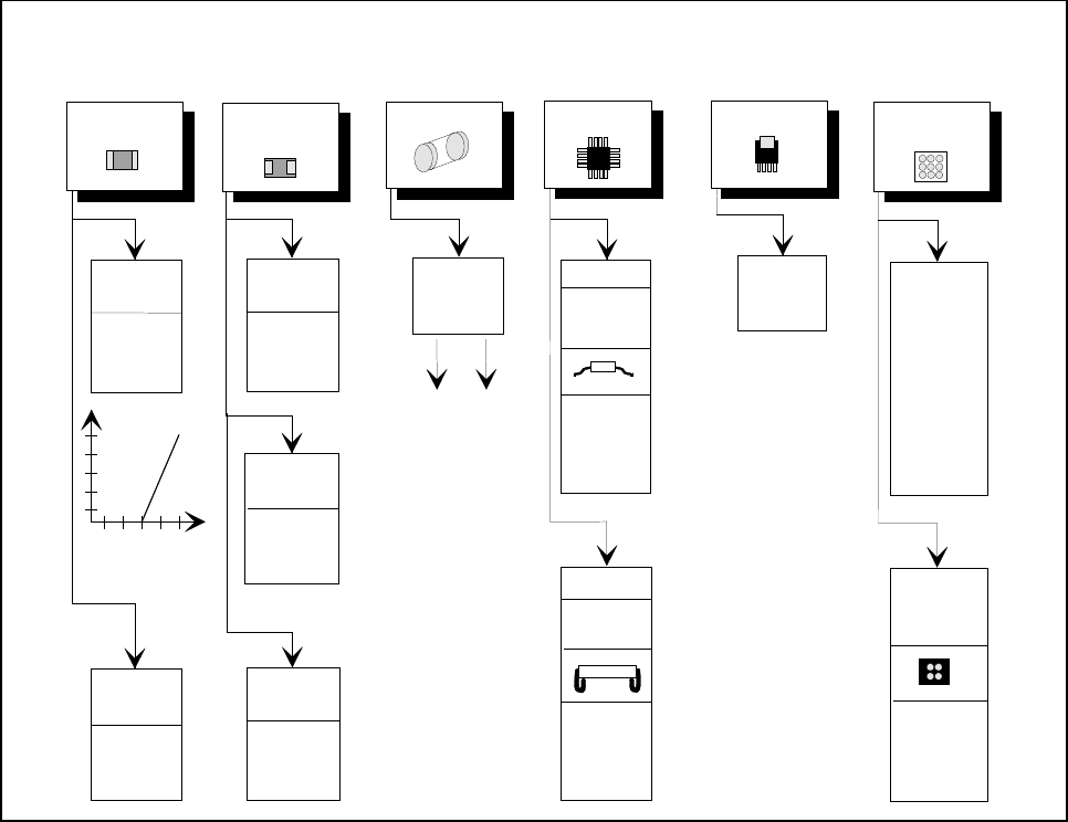
Fig. 5.7.7 Illumination parameters for standard components at the 12x revolver head camera
5.7.6.4 Settings for Illuminating Other Components
Fig. 5.7.8 presents a list of the illumination settings for other components.
flat: 255
middle: 90
steep: 60
Diagram for adjusting the illumination of standard components
Chip
IC
Power IC
Melf BGA, µBGA
flip-chip
Tantalum
capacitor
BGA,
µBGA,
flip-chip
0805 and
larger
0402,
0603
Light
General
flat: 120
middle: 40
steep: 170
Reflective
body
flat: 120
middle: 100
steep: 100
flat: 70
middle: 60
steep: 150
Gullwing
SO, SOT,
TSOP
QFP,
flat: 170
middle: 50
steep: 120
flat: 0
middle: 10
steep: 170
flat: 255
middle: 120
steep: 10
flat: 170
middle: 60
steep: 120
J-Lead
PLCC
flat: 80
middle: 40
steep: 120
Ceramic
BGA
flat: 0
middle: 50
steep: 255
flat: 255
middle: 20
steep: 0
Illumination
level
Brightness
150
255
Contrast
graduation
5 Vision Functions SIPLACE 80S-20/F4/F4-6/F5 User’s Manual
5.7 Guidelines for Describing Package Forms Edition 03/98 from Software Version SR.404.xx
5 - 132 Line engineer
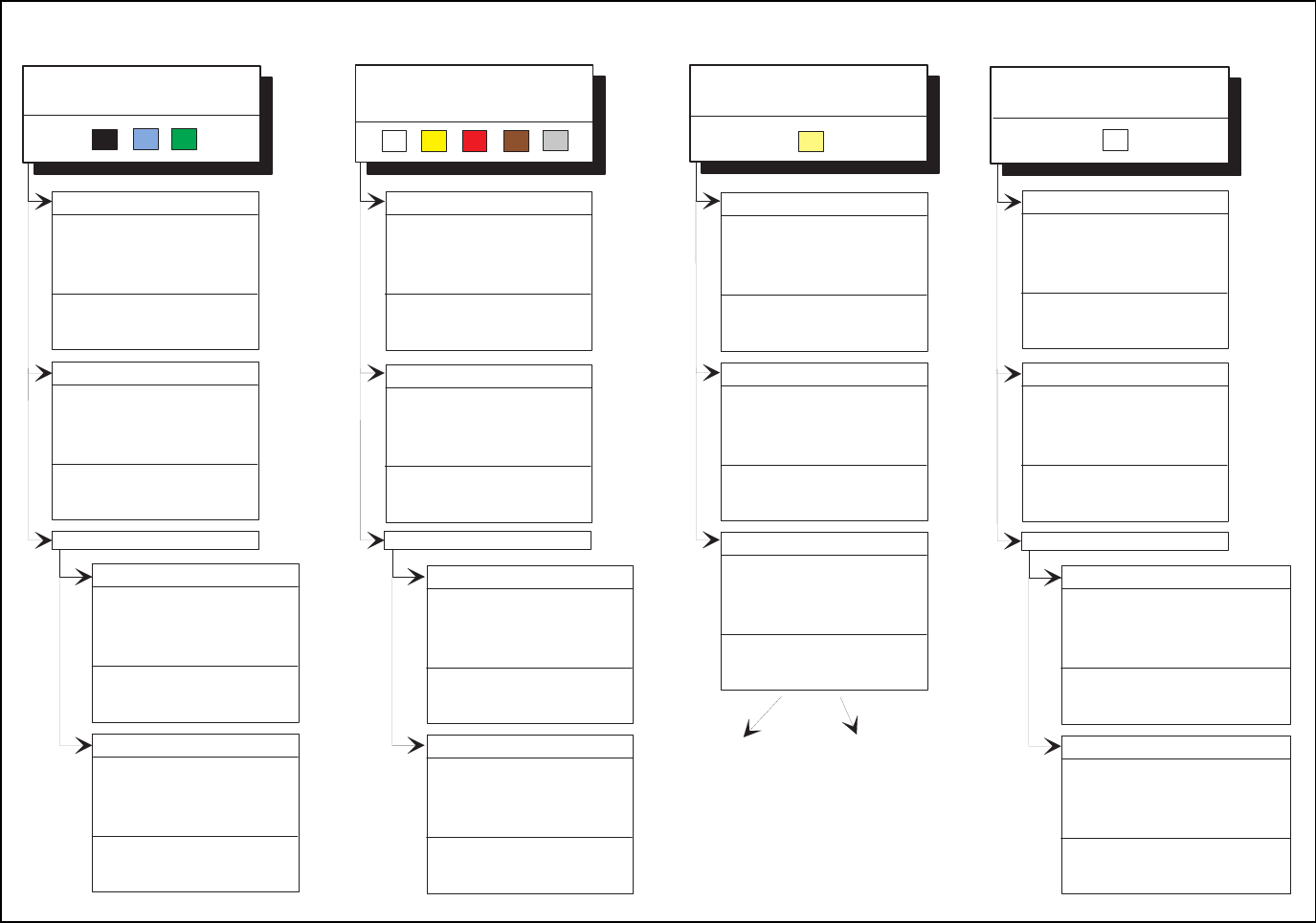
Fig. 5.7.8 Illumination parameters for other components at the 12x revolver head camera
Adjusting the illum ination of other com ponents
Light and dull body
( w hite, yellow , red, brow n, grey,
m e ta llic d u ll )
Ceram ic body
Dark and dull body
( black, blue, green )
Reflective body
(independently of color and m aterial)
D u ll le a d s
flat: 70
middle: 60
steep: 150
Visual separation betw een leads
and body is not possible.
Illum inate body and leads equally.
M easure outline.
S h in y le a d s
C lear separation
betw een leads
and body.
D u ll le a d s
fla t: 1 5 0
m id d le : 1 2 0
s te e p : 0 - 2 0
S h in y le a d s
1. Illum inate body and leads equally.
M easure outline.
2 . T ric k : U s e fla t a n d m id d le le v e ls to
b rin g le a d s im a g e to s a tu ra tio n .
M easure.
C le a r s e p a ra tio n
betw een leads
and body.
fo r v a ria n t 2 : fla t: 1 5 0 - 2 5 5
m id d le : 6 0 - 1 5 0
s te e p : 0 - 2 0
fla t: 2 0 0
middle: 80
steep: 0 - 20
fla t: 1 2 0
middle: 80
steep: 0 - 20
C le a r s e p a ra tio n
betw een leads
and body.
C lear separation
betw een leads
and body.
J-Lead ( PLC C ), convex-type leads
G u llw in g le a d s ( S O , Q F P )
D u ll le a d s
S h in y le a d s
fla t: 1 2 0
middle: 50
steep: 170
fla t: 1 7 0
middle: 50
steep: 120
C le a r s e p a ra tio n
betw een leads
and body.
C lear separation
betw een leads
and body.
J-Lead ( PLC C ), convex-type leads
G u llw in g le a d s ( S O , Q F P )
fla t: 1 7 0
middle: 50
steep: 120
flat: 80
middle: 40
steep: 120
C le a r s e p a ra tio n
betw een leads
and body.
C le a r s e p a ra tio n
betw een leads
and body.
O ther lead shapes
D u ll le a d s
fla t: 1 7 0
middle: 50
steep: 120
Visual separation betw een leads
and body is not generally possible.
S h in y le a d s
fla t: 0
m iddle: 0 - 10
steep: 100 - 255
C lear separation
betw een leads
and body.
fla t: 0
m iddle: 0 - 10
steep: 150 - 255
Leads:
O u tlin e :
M easuring m ethod:
Visual separation betw een leads
and body is not possible.
Illum inate body and leads equally.
M easure outline.
fla t: 1 7 0
m iddle: 50
steep: 120
Visual separation betw een leads
and body is not possible. M easure
outline or lead tips. Leads are
outside the body.
flat: 80
middle: 40
steep: 120
J-Lead ( PLC C ), convex-type leads
G u llw in g le a d s ( S O , Q F P )
O ther lead shapes
C onvex-type leads
flat: 70
middle: 60
steep: 150
O ther lead shapes
fla t: 0
m iddle: 0 - 20
steep: 200 - 255
Visual separation betw een leads
and body is not generally possible.
Illum inate body and leads equally.
M easure outline.
Illum ination level B rightness