80S-2080F480F4-680F5 User’s Manual.pdf - 第362页
SIPLACE 80S-20/F4/F4-6/F5 User’s Manual 5 Vision Functi on s Edition 03/98 from S oftware Version SR.404.xx 5.7 Guidelines for Describing Package Form s Line engi neer 5 - 141 5.7.8.2 Pseudo color representation The pseu…

5 Vision Functions SIPLACE 80S-20/F4/F4-6/F5 User’s Manual
5.7 Guidelines for Describing Package Forms Edition 03/98 from Software Version SR.404.xx
5 - 140 Line engineer
5.7.7.6 General Information on Setting Illumination Values
– As a rule it is better to overilluminate the component than to underilluminate it. A saturated image is prefer-
able to a low-contrast image.
– Optimum illumination is attained when only the leads are imaged and the component body is not shown.
– If you cannot clearly separate the image of the component body from the leads, we recommend to illumi-
nate body and leads equally and then to measure the outline.
5.7.8 Setting the Components Illumination at the 6x Revolver Head
Camera (Standard vision system)
5.7.8.1 General Information on Illumination Methods
The idea of illumination setting is to obtain an image of the leads of a component which is as high-contrast as
possible. At the same time it is also important to suppress representation of the body of the component.
These instructions are intended to help you find the best possible illumination parameters. This, however,
does not imply that you rigidly comply with the values specified in these instructions. The way you should pro-
ceed is first to follow these instructions and then to adjust the parameters yourself where necessary. It may
well be that you come across one or other component the leads of which are better illuminated using values
different to the ones suggested in these instructions.
The illumination system comprises three different illumination levels. The intensities can be programmed indi-
vidually. By using the individual illumination levels one at a time or in combination with one another you can
adapt the illumination to suit a wide range of components.
Flat illumination level
The flat illumination level is used for illuminating BGAs, µBGAs, flip-chips, J-lead components (PLCC), Melfs
and components with convex-type leads. It tends to emphasize body and lead edges. It is, however, less suit-
able for displaying bright component bodies and ceramic components.
Steep illumination level
The main application for the steep illumination level is for reflective leads, ceramic components and bright
component bodies. It is less suitable for reflective component bodies, flip-chips or µBGAs.
NOTE
Most components will require a combination of these three illumination levels to achieve optimum illumination.
Using
one
illumination level will only be successful in exceptional cases.
SIPLACE 80S-20/F4/F4-6/F5 User’s Manual 5 Vision Functions
Edition 03/98 from Software Version SR.404.xx 5.7 Guidelines for Describing Package Forms
Line engineer 5 - 141
5.7.8.2 Pseudo color representation
The pseudo color representation provides a powerful and objective assessment of the illumination, by repre-
senting a brightness value in a color.
A contrast of at least 4 color scales between the lead and body is required for a measurement. In the ‘Illumina-
tion’ menu of the package form manipulator, components are displayed in the pseudo color representation on
the station computer monitor.
5.7.8.3 Settings for Illuminating Components
The standard range of components includes chips (0603 to 2220), tantalum capacitors, Melf components,
PLCCs, QFPs, SOs, SOJs, TSOPs, ICs, power components, flip-chips, µBGAs and BGAs.
For the components which are listed below the GF interpreter in the station computer uses the default illumi-
nation parameters listed in Fig. 5.7.11:
– Chips (0603 to 2220)
– Tantalum capacitors (component bodies, non-reflective)
– Melf
– PLCC, QFP, SO, SOJ, TSOP, ICs, power ICs
– Flip-chips, µBGAs, BGAs
The special components include:
– Power transistors
– Plugs
– PLCC base
– Quartz timers
As a rule you will not need to change the illumination parameters for the components.
Color scale Brightness
white light
yellow
orange
red
brown
green
light blue
blue
violet
black dark
Tab. 5.7.5 Conversion table for the pseudo color representation at the 6x revolver head
5 Vision Functions SIPLACE 80S-20/F4/F4-6/F5 User’s Manual
5.7 Guidelines for Describing Package Forms Edition 03/98 from Software Version SR.404.xx
5 - 142 Line engineer
.
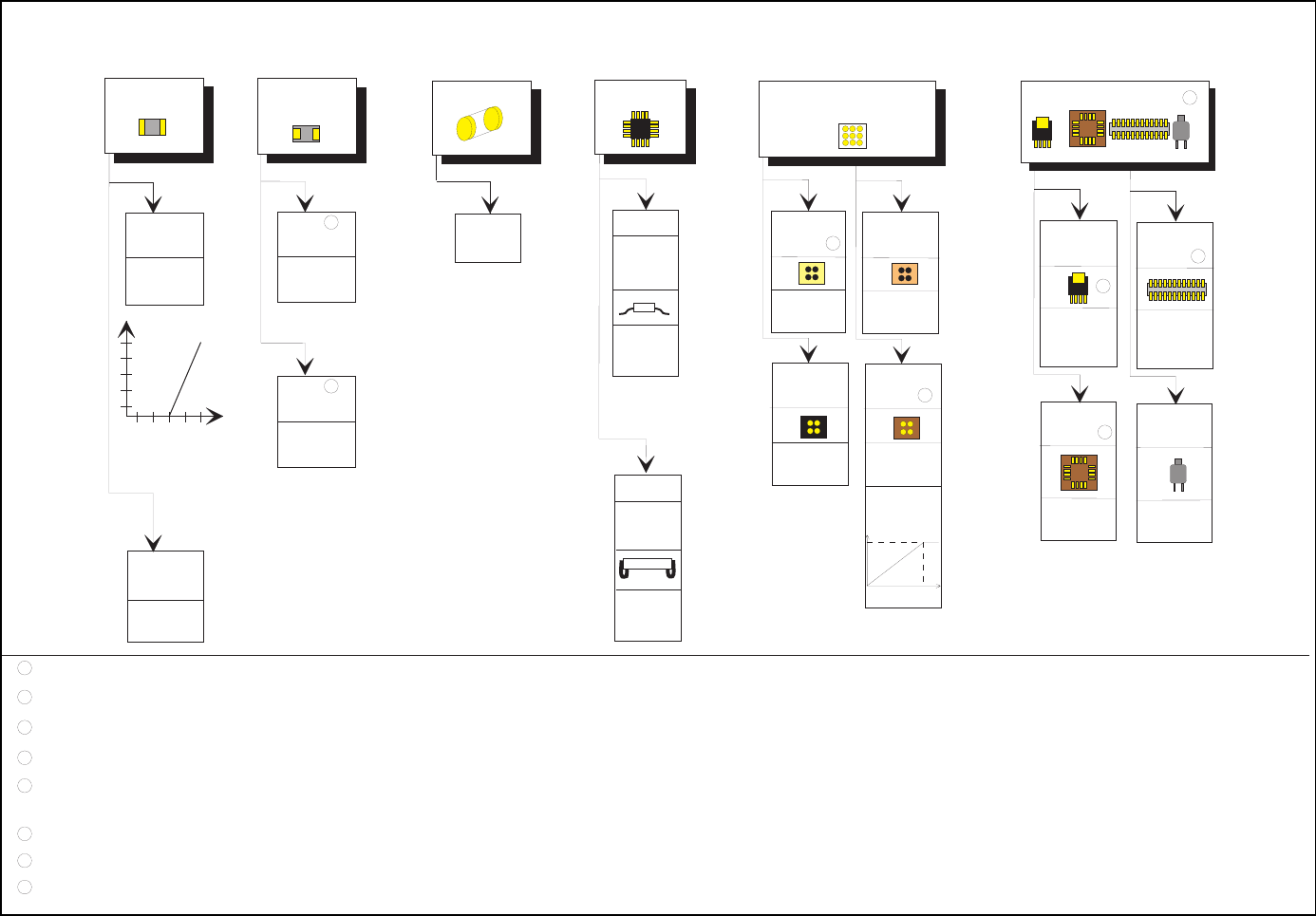
Fig. 5.7.11 Illumination parameters for components at the 6x revolver head camera (32x32)
D ia g r a m fo r a d ju s tin g th e illu m in a tio n o f c o m p o n e n ts
Chip
IC
Melf
BGA
Tantalum
capacitor
fla t: 1 5 0
steep:150
J-Lead
PLCC
fla t: 7 0
steep: 140
Ceram ic
BGA
fla t: 0
steep: 255
Plastic
BGA
0805 and
larger
fla t: 2 0 0
steep: 120
0603
fla t: 1 5 0
steep: 200
G eneral
fla t: 1 2 0
steep: 150
fla t: 2 5 5
steep: 130
fla t: 2 0 0
s te e p : 0
G u llw in g
SO, SO T,
TSO P
QFP,
Special com ponents
Power
transistor
fla t: 2 5 5
steep: 150
PLCC-
socket
fla t: 0 - 3 0
steep:150-200
Plug
fla t: 0
steep: 150-200
Q uartz
fla t: 2 0 0
steep:120-180
TBG A
re fle c t. b o d y
fla t: 2 0 0
s te e p : 0
TBG A
dull
fla t: 0
steil:150-200
approx. 180
255
If necessary,
use the LU T
below
1
Reflect.
body
fla t: 2 5 5
steep: 40
8
6
2
7
5
3
4
6
1
2
3
4
5
D o not use for reflective com ponents.
U se negative ball contrast w hen m apping the ball.
The description m ust only contain the innerm ost row of balls. U se negative contrast.
It m ust be possible to insert the com ponents. The test m ust be carried out for each type.
7
The edge of the large cooling surface is extrem ely irregular on som e types on account of the production m ethods used.
If you are unsure, do not use it for the m easurem ent
U p to PLC C 52 base. M ake sure that you are using the correct nozzle.
D escribe as for a BG A , if necessary.
8
D escribe as for an FD C . M easuring m ode: size+ lead
150
255
C ontrast
graduation