80S-2080F480F4-680F5 User’s Manual.pdf - 第381页
5 Vision Functions SIPLACE 80S-20/F4/F4-6/F5 User’s Manual 5.10 Test Component: Supplements to the 80F4, 80F4-6 or 80F5 Machines Ed ition 03/98 from Software Version SR.404.xx 5 - 160 Line engine er Fig. 5.10.4 Test comp…
SIPLACE 80S-20/F4/F4-6/F5 User’s Manual 5 Vision Functions
Edition 03/98 from Software Version SR.404.xx 5.10 Test Component: Supplements to the 80F4, 80F4-6 or 80F5 Machines
Line engineer 5 - 159
With the mouse pointer mark a component from the list field or the vision system in the Camera type
options field.
Click on the Load GF data button. The data are transferred to the program.
Click on the Main view symbol, break off the dialog without saving and return to the Main view menu.
5.10.2
Test Component
Menu
5.10.2.1
Select Component Type
Option
With the 80F
4
, 80F
4
-6 or 80F
5
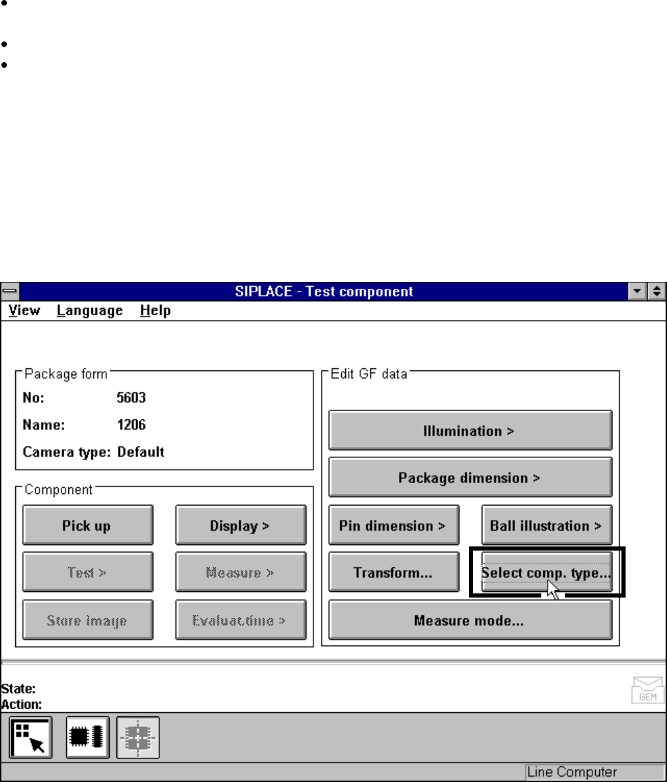
machines, the Test component menu (for a description see Section 5.10.2,
Page 5 - 159) also includes the Select component type option.
Fig. 5.10.3 Test component menu (80F
4
, 80F
4
-6 or 80F
5
)
When you select this option the following menu will open.
5 Vision Functions SIPLACE 80S-20/F4/F4-6/F5 User’s Manual
5.10 Test Component: Supplements to the 80F4, 80F4-6 or 80F5 Machines Edition 03/98 from Software Version SR.404.xx
5 - 160 Line engineer
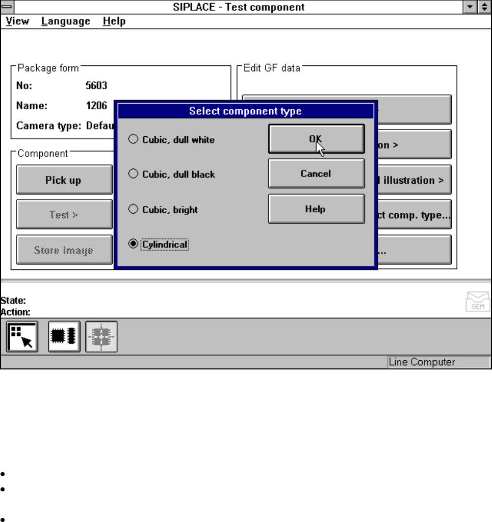
Fig. 5.10.4 Test component menu, Select component type option
You should select this option when centering errors occur with standard lighting. The 4 possibilities available
here for selection enable you to match the lighting optimally to the component in question. Each of these
options contains certain combinations of the flat, middle and steep types of illumination.
Mouse functions
Use the mouse pointer to mark the corresponding component type.
With OK confirm your input and the option field will be closed. You will be returned to the Test component
menu.
Click on Cancel to quit the option field without taking over any modifications you may have changed.
SIPLACE 80S-20/F4/F4-6/F5 User’s Manual 5 Vision Functions
Edition 03/98 from Software Version SR.404.xx 5.11 Coplanarity Laser Module (SIPLACE 80F4, 80F4 -6 or 80F5 only)
Line engineer 5 - 161
5.11 Coplanarity Laser Module
(SIPLACE 80F
4
,
80F
4
-6 or 80F
5
only)
5.11.1 Description of Functioning
The coplanarity laser module is used for measuring vertical bending in the connection leads of components.
The leads height is measured by a non-contact method working on the principle of laser triangulation.
The placement head picks up the component which is to be checked, centers it optically with the IC camera
and then moves each of its four sides in turn over the stationary laser beam of the coplanarity laser module.
Here each lead is scanned from the bottom up by the laser beam. The laser light scattered by the underside of
the leads is detected by a sensor and serves as a basis for calculating the exact position of the lead with
respect to the board. The positional values thus obtained are then compared with the limit value specified by
the user. If this value is exceeded, the component will be discarded or returned.
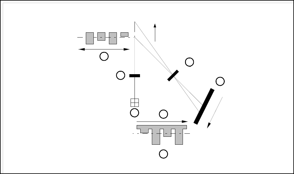
Fig. 5.11.1 Laser triangulation principle of measurement
- Key to Fig. 5.11.1
1 Receiver lens 2 Detector
3 Measurement signal 4 Time t
5 Laser 6 Transmitter lens
7 Direction of travel
The coplanarity laser module is used in combination with optical component centering using the vision sys-
tem. Components with bent or missing leads will be detected and discarded as appropriate.
1
2
3
4
5
6
7
z = 0
+Z
+Z’
Z’ = 0