80S-2080F480F4-680F5 User’s Manual.pdf - 第455页
9 Maintenance SIPLACE 80S-20/F4/F4-6/F5 User’s Manual 9.1 Overview Edition 03/98 from S oftware Version SR.404.xx 9 - 6 9.1.4 General Information (SIPLACE 80S-20, 80F 4 and 80F 4 -6/80F 5 ) 9.1. 4.1 Safet y Inst ructions…
SIPLACE 80S-20/F4/F4-6/F5 User’s Manual 9 Maintenance
Edition 03/98 from Software Version SR.404.xx 9.1 Overview
9 - 5
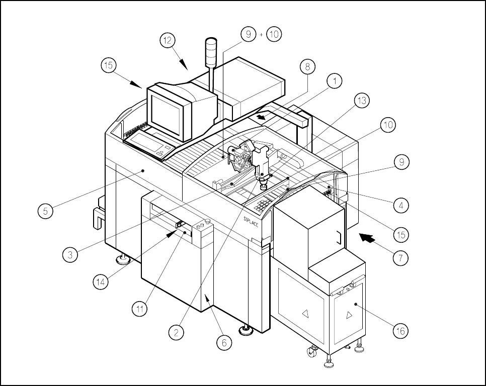
9.1.3 SIPLACE 80F
4
-6/F
5
Placement Machine
Fig. 9.1.3 SIPLACE 80F
4
-6/F
5
: Modules requiring maintenance
- Key to Fig. 9.1.3
1 6 x revolver head, gantry 1 10 Empty tape cutters
2 IC head 11 PCB transport
3 X axis, gantry 1 12 Rejects container for the revolver head
4 Y axis, gantry 1 13 Rejects container for IC head, component
5 Safety hoods with guide rails vision camera, coplanarity laser module
6 Compressed air unit and nozzle changer
7 Servo unit, filter mat 14 Control unit of PCB Handling
8 Control unit, filter mat 15 Bar code strips
9 Changeable components tables 16 Wafflepack changer
9 Maintenance SIPLACE 80S-20/F4/F4-6/F5 User’s Manual
9.1 Overview Edition 03/98 from Software Version SR.404.xx
9 - 6
9.1.4 General Information (SIPLACE 80S-20, 80F
4
and 80F
4
-6/80F
5
)
9.1.4.1 Safety Instructions
DANGER
• When carrying out any work you must comply with the safety instructions in this user’s manual.
• The key-operated switch may be unlocked only by authorized persons and once work is completed
the key must be kept under lock.
• Do not carry out any cleaning work with alcohol in the presence of naked lights or fire.
• Always keep to the order of work specified.
DANGER
The coplanarity laser module can be installed as an option on Siplace 80F
4
, 80F
4
-6 and 80F
5
automatic
placement systems. The laser operates within a power and wavelength range which is hazardous for the skin
and eyes. For this reason special safety rules apply; see also the Section 9.9.5 on page 9 - 100.
Do not tamper in any way whatsoever with the safety devices!
Fault correction and repairs to the laser module and safety plug must be carried out by the manufacturer.
9.1.4.2 Information on the Sequence of Work
NOTE
The maintenance frequencies specified for the checking and replacing the filter elements apply only for the
specified compressed air quality, see Compressed Air Specification. Otherwise increase maintenance fre-
quencies accordingly.
Make a note in the maintenance schedule of the maintenance work which has been carried out.
We recommend you keep to the sequence of work specified in the maintenance schedule.
NOTE
If you wish to move the gantry by hand after switching off the SIPLACE 80F
4
or 80F
4
-6 or 80F
5
placement
machine it is essential that you observe the following information:
The z axis (sleeve) must be in its top end position after the machine is switched off. If this is not the case, this
indicates a fault. You should inform the SMD service department.

SIPLACE 80S-20/F4/F4-6/F5 User’s Manual 9 Maintenance
Edition 03/98 from Software Version SR.404.xx 9.1 Overview
9 - 7
For various types of maintenance work you will require the ’Gantry 1 functions’ or ’Gantry 2 functions’
menu.
For details regarding these menus please refer to Chapter 4.
When you change over from the ’Gantry 1 functions’ menu to the ’Gantry 2 functions’ menu or when you
quit the ’Gantry functions’ menu, with the SIPLACE 80S-20, 80F
4
, 80F
4
-6 and 80F
5
machines only a head
reference run will be carried out and no gantry reference run. This head reference run does not include
either a vacuum test or a height reference run.
For this reason, after any maintenance work during which sleeves were removed from the star, always
select the ’Vacuum test revolver head’ menu, doing so before you quit the ’Gantry x functions menu’:
Check the assignments of the nozzle sizes to their places of installation and the vacuum reached in each
case. This information will be displayed on the screen. After this, for the height reference run select the
’Revolver head nozzle offset’ menu and then quit the ’Gantry x functions’ menu.
If, under the ’Gantry x functions’ menu, you have opened the safety hood and moved the gantry by hand
then the gantry will return at a lower speed to its starting position once the safety hoods have been closed
and the start button pressed.
9.1.4.3 Protective Functions in the
Gantry X Functions
Menu
The power to the portal and head axes is switched off when you select the ‘Gantry X functions‘ menu, fol-
lowed by the ‘Gantry functions‘ menu.
When you open the protective covers, the operating voltage for the coplanarity laser module on the
SIPLACE 80F
4
, 80F
4
-6 or 80F
5
automatic placement systems is switched off.
The key switch must be set to ‘Set-up mode‘ by an authorized person and then locked again before any
work is carried out using the ’Gantry X functions’ menu.
The x and y gantry axes will only be switched on when this is required for the selected function. Here, after
being so requested on the screen, you must close the safety hoods and press the start button.
All other ’Gantry x functions’ can be used when the cover is open provided the key-operated switch is
unlocked. This includes, for example, the function ’Star step’ for sleeve removal. The x and y gantry axes
are disabled.