80S-2080F480F4-680F5 User’s Manual.pdf - 第471页
9 Maintenance SIPLACE 80S-20/F4/F4-6/F5 User’s Manual 9.3 Machine Base Ed ition 03/98 from Software Version SR.404.xx 9 - 22 9.3.3.6 Refitting t he Feeder M o dules Remove th e cover st rips over the comp ressed ai r dis…
SIPLACE 80S-20/F4/F4-6/F5 User’s Manual 9 Maintenance
Edition 03/98 from Software Version SR.404.xx 9.3 Machine Base
9 - 21
9.3.3.3 Cleaning the Feeder Modules, Clearing Loose Components
Remove the tapes and with the vacuum cleaner thoroughly clean the surface of the modules, particularly
the area of the tape guide.
9.3.3.4 Oiling the bearing surface for the feeder modules
The bearing surface should be lightly oiled every time a feeder module is changed.
Apply a small quantity of WD40 corrosion protection agent to a clean cloth and rub it over the module bear-
ing surface on the components table. Remove excess WD40 and replace the module in the track.
9.3.3.5 Maintenance of the Magnetic Strips and Bearing Surfaces of the Feeders
DANGER
Do not carry out any cleaning work with alcohol in the presence of naked lights or fire!
Caring for the magnetic strips
The feeder modules are removed from the components table (see Section 9.3.3.1).
NOTE
The compressed air distributor strip on the components table is used for connecting the bulkcase feeders.
This strip runs parallel to the board conveyor and has upward-pointing open nozzles. Make sure that the
nozzles do not get contaminated with oil or come into contact with grease. Grease, oil or dirt will lead to
feeder malfunctions or components on the feeder will be rendered unusable.
Cover the nozzles of the distributor strip with insulation tape, for example.
Check the surface of the components table magnetic strips for damage or scratches.
If necessary, work over the surface with an oilstone and then wipe the magnetic strip with a cloth soaked in
alcohol.
Apply a small quantity of WD40 corrosion protection agent to the magnetic strip with a cloth.
Cleaning and oiling the bearing surfaces of the feeders
Wipe the bearing surfaces of the feeder modules on the components table with a cloth soaked in alcohol.
Apply a small quantity of WD40 corrosion protection agent to the magnetic strip with a cloth.
9 Maintenance SIPLACE 80S-20/F4/F4-6/F5 User’s Manual
9.3 Machine Base Edition 03/98 from Software Version SR.404.xx
9 - 22
9.3.3.6 Refitting the Feeder Modules
Remove the cover strips over the compressed air distributor block.
Replace the feeder modules back into the correct track on the components table.
Replace the tapes in the module (see the Component supply section of this user’s manual).
NOTE
If you are not certain of the assignment of the rolls to the division, have the location’s set-up displayed in
this way : Set-up menu → Setup location no. Further information in this connection will be found in the
Components Handling section of this user’s manual.
Close the safety hoods.
In the PCB transport menu select the Conveyor width option and set the conveyor back to the width of
the board which is to be processed.
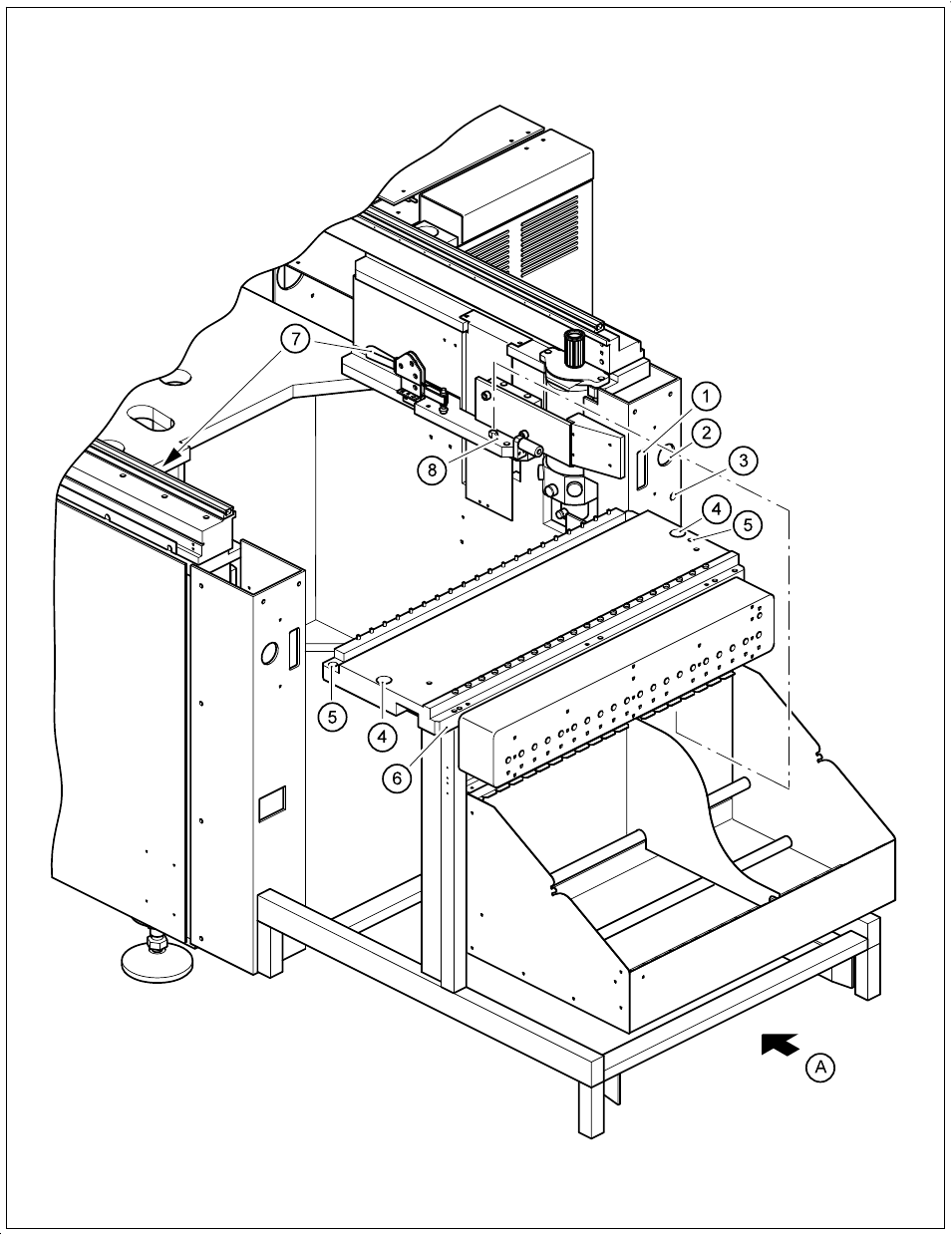
9.3.3.7 Removing and installing the component table
Move the portal to the opposite side of the table.
DANGER
Switch off the automatic placement system and disconnect from the power supply.
WARNING
Disconnect the automatic placement system from the compressed air supply.
Disconnect the mains plug for the component table 2.
Remove the communication plug 1.
If necessary, disconnect the compressed air supply from the component table 3.
Push the platform truck under the component table (A).
Loosen the two hexagon socket head screws for fixing the component table 5.
Open the horizontal tensioner 7.
Carefully raise the component table with the platform truck until the centering pins are
«
outside the holes.
Then pull out the component table.
Dismantle the cutter from the used tape chute.
Reverse the above sequence to reassemble.
SIPLACE 80S-20/F4/F4-6/F5 User’s Manual 9 Maintenance
Edition 03/98 from Software Version SR.404.xx 9.3 Machine Base
9 - 23
Fig. 9.3.2 Removing the components table