80S-2080F480F4-680F5 User’s Manual.pdf - 第475页
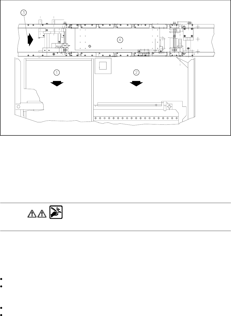
9 Maintenance SIPLACE 80S-20/F4/F4-6/F5 User’s Manual 9.3 Machine Base Ed ition 03/98 from Software Version SR.404.xx 9 - 26 Fig. 9.3.3 Wafflepack change r or component ch angeover table - Key to Fig. 9.3.3 1 Waf flepack…

SIPLACE 80S-20/F4/F4-6/F5 User’s Manual 9 Maintenance
Edition 03/98 from Software Version SR.404.xx 9.3 Machine Base
9 - 25
NOTE
In order to avoid them being damaged, position placement heads 1 and 2 within the PCB transport area. To
do so, slide the corresponding gantry by hand by pressing against a side of the gantry. When carrying out
maintenance work make particularly sure before you switch on the 80S-20 machine that you have the at least
the minimum separation between the gantries. For this reason always position only one gantry by hand over
the board conveyor and then carry out maintenance work on the corresponding empty tape cutter.
Preparatory work
DANGER
• Switch the automatic placement system off at the main switch and disconnect from the power supply.
• Switch off the compressed air supply using the shut-off valve on the compressed air unit.
WARNING
• Wait until the compressed air lines have depressurized. This is indicated when the
cutter bar swings in towards the cutting wheel.
Open the protective covers and the side swivel doors.
Move the corresponding gantry out of the working range.
Remove
– the corresponding component changeover table from the 80 S placement system (see Section
9.3.3.7)
– the corresponding component changeover table from the 80 F placement system (see Section
9.3.3.7) and if a waffle-pack changer is installed, the waffle-pack changer (see Section 9.8).
NOTE
If the wafflepack changer has not yet been run to empty, the assignment of the trays to the track and the
rotational position of the magazines to the trays must not be changed.
Remove the guard plate of the cutter.
9 Maintenance SIPLACE 80S-20/F4/F4-6/F5 User’s Manual
9.3 Machine Base Edition 03/98 from Software Version SR.404.xx
9 - 26
Fig. 9.3.3 Wafflepack changer or component changeover table
- Key to Fig. 9.3.3
1 Wafflepack changer
2 Changeable component table
3 Direction of PCB transport
4 Center conveyor
Checking and replacing the cutter blade and rotary cutter
WARNING
Do not touch the cutting edge of the cutter blade or you risk cutting yourself !
Carry out a visual inspection of the cutter blade and rotary cutter. If the cutting edge is blunt or the cutter blade
in the rotary cutter has worn out, you will need to replace
both
parts each time, as is described in the Compo-
nents table section of the service manual. Setting will be required here.
Cleaning and oiling the guide rail, greasing the rotary cutter carriage
There is a risk of cutting yourself on the cutting edge! Wear sturdy work gloves.
Clean the guide rail (see Fig. 9.3.4, page 9 - 27) with alcohol. In particular remove accumulations of
grease and dirt at either end of the carriage path. Apply some WD40 lubricant and corrosion protection
agent.
To allow you to reach all points, slide the carriage with the rotary cutter by hand.
Use a brush to apply some WD40 lubricant and corrosion protection agent to the rotary cutter and cutter
blade.
SIPLACE 80S-20/F4/F4-6/F5 User’s Manual 9 Maintenance
Edition 03/98 from Software Version SR.404.xx 9.3 Machine Base
9 - 27
Grease the two lubrication nipple of the rotary cutter carriage (see Fig. 9.3.4, page 9 - 27) with a small
quantity of Urethyn E/M2 (approx. 0.5 g + 0.25 g per lubrication nipple). Use the grease gun to do this.
Finally, slide the carriage with the rotary cutter repeatedly back and forth along the guide rail in order to
spread the grease evenly over the lateral guide faces of the guide rail.
Greasing the toothed belt
Use some Staburags N12 to lightly grease the toothed belt for moving the rotary cutter carriage (see Fig.
9.3.4, Page 9 - 27) and the toothed belt for the rotary movement of the rotary cutter (see Fig. 9.3.4, Page
9-27).
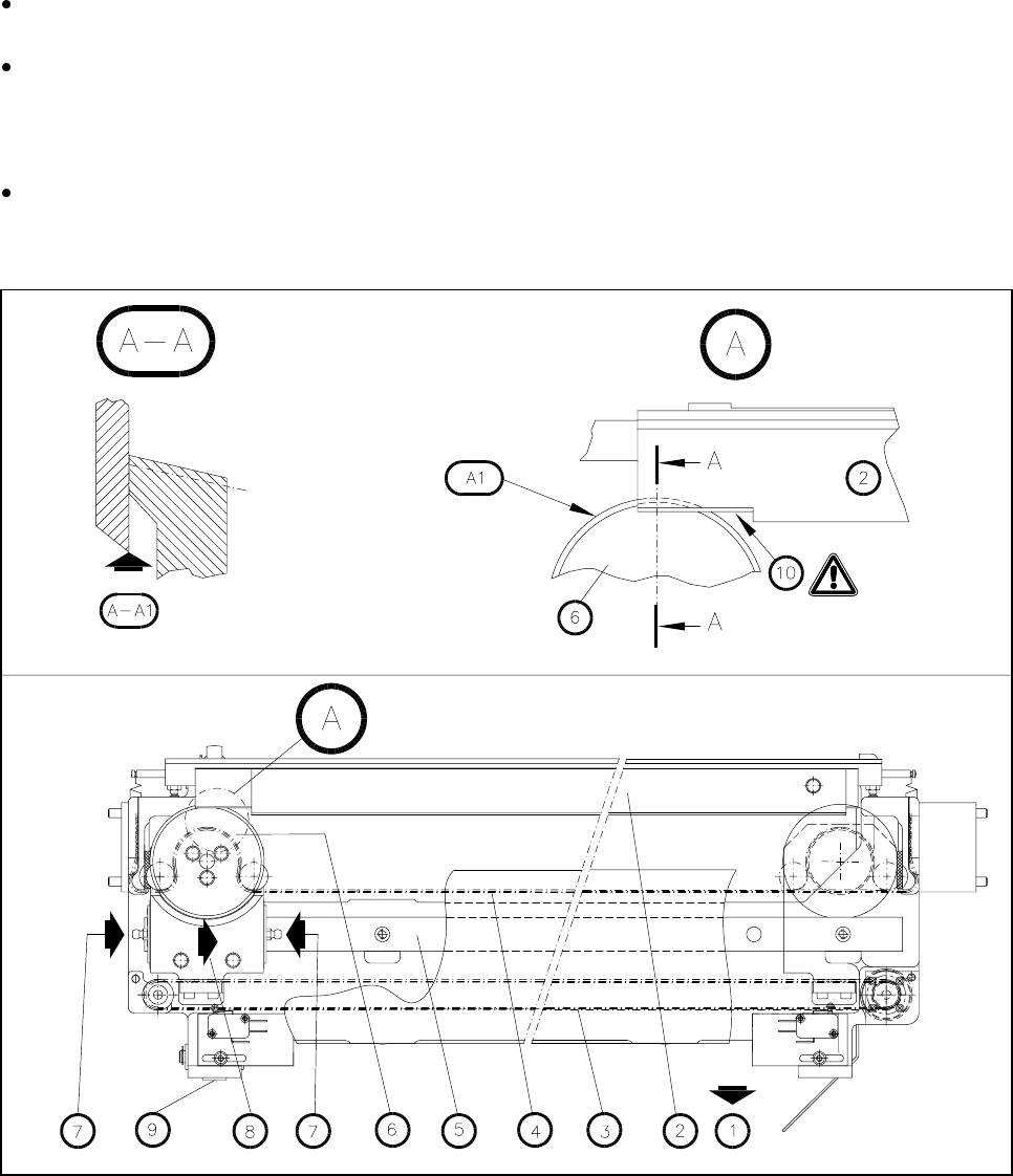
Fig. 9.3.4 Maintenance of the empty tape cutter (the empty tape guide channel has been removed)
- Key to Fig. 9.3.4:
1 Removal of the changeable components table
2 Cutter blade
3 Toothed belt for moving the rotary cutter carriage
4 Toothed belt for the rotary movement of the rotary cutter
5 Guide rail
6 Rotary cutter
7 Lubrication nipple