80S-2080F480F4-680F5 User’s Manual.pdf - 第489页
9 Maintenance SIPLACE 80S-20/F4/F4-6/F5 User’s Manual 9.3 Machine Base Ed ition 03/98 from Software Version SR.404.xx 9 - 40 Fig. 9.3.9 Replacing cutting edges on the used tape cutter - Key to Fig. 9.3.9 1 Fixed c utting…
SIPLACE 80S-20/F4/F4-6/F5 User’s Manual 9 Maintenance
Edition 03/98 from Software Version SR.404.xx 9.3 Machine Base
9 - 39
9.3.9.2 Replacing the cutting edges of the fixed or moving cutting blades
DANGER
Switch off the automatic placement system and disconnect from the power supply.
WARNING
Disconnect the automatic placement systems from the compressed air supply.
If there is a wafflepack changer installed, remove it first (see Section 9.8, Page 9 - 91).
Remove the component table (see section 9.3.3.7, Page 22).
Remove the used tape channel.
PLEASE NOTE
Always replace the cutting edges of the fixed and moving cutting blades at the same time since the two cutting
blade are mechanically matched to one another.
Loosen the two M6x30 hexagon socket head screws (point 2, Fig. 9.3.9) for fixing the fixed cutting blade
Raise the blade and mark the previously used cutting edge.
Loosen the two M4x25 hexagon socket head screws (point 4, Fig. 9.3.9) for fixing the moving cutting
blades. Use an SW 10 spanner to secure the square spacer (point 5, Fig. 9.3.9) to prevent it turning.
Turn the moving cutting blade you have removed 180° about the A-B axis (point A, Fig. 9.3.9).
Fix the moving cutting blade. Use the spanner to secure the square spacer (point
ƒ
, Fig. 9.3.9) to prevent it
turning.
Turn the fixed cutting blade about the A-B axis, 180° from the original position (point B, Fig. 9.3.9).
Fix the fixed cutting blade.
Remove the used tape channel and the component table.
Reinstall the wafflepack changer, if necessary.
9 Maintenance SIPLACE 80S-20/F4/F4-6/F5 User’s Manual
9.3 Machine Base Edition 03/98 from Software Version SR.404.xx
9 - 40
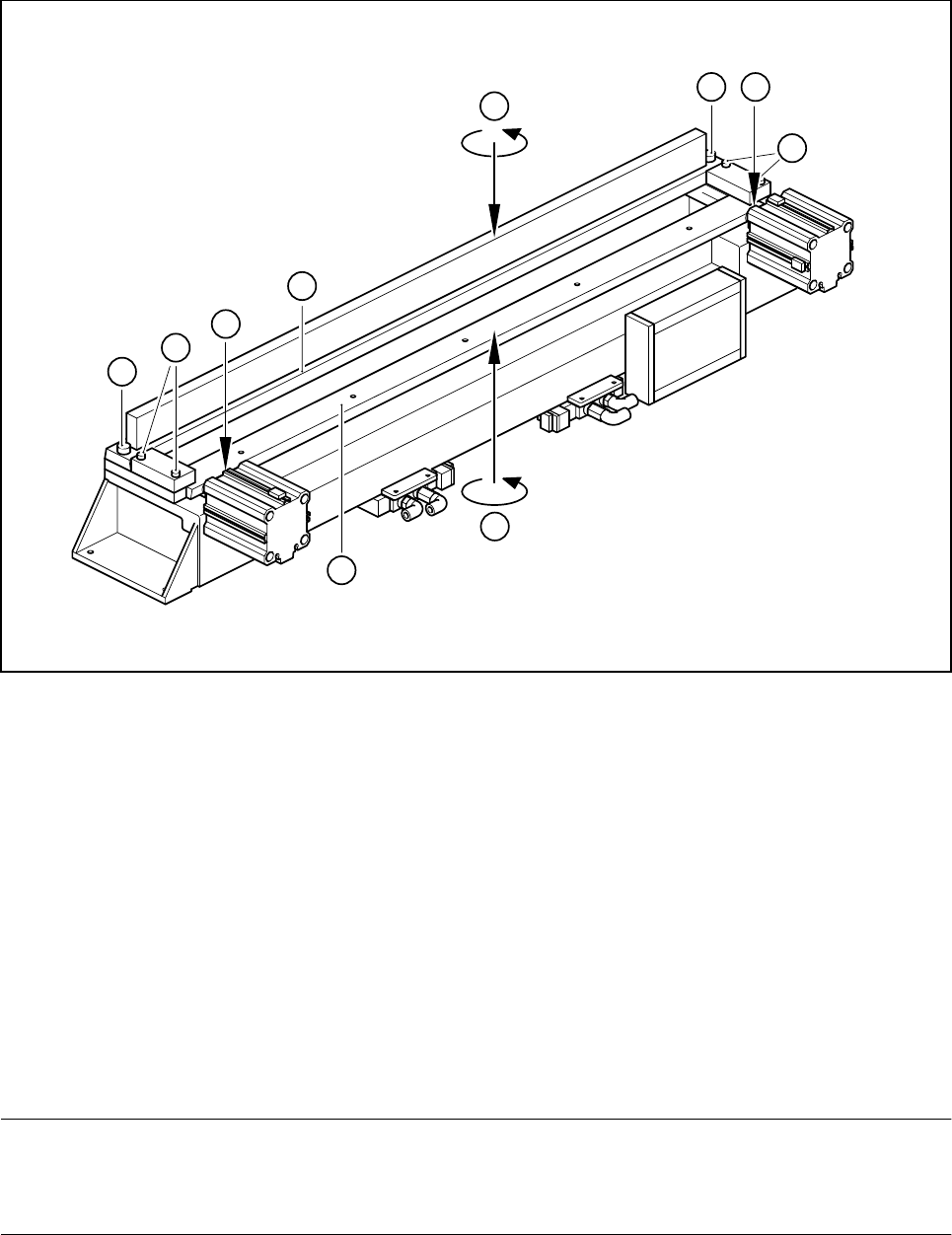
Fig. 9.3.9 Replacing cutting edges on the used tape cutter
- Key to Fig. 9.3.9
1 Fixed cutting blade
2 M6x30 hexagon socket head screw for fixing the fixed cutting blades
3 Moving cutting blade
4 M4x25 hexagon socket head screw for fixing the moving cutting blades
5 10x10 square spacer
A Turn the moving cutting blade through 180°
B Turn the fixed cutting blade through 180°
9.3.9.3 Replacing the fixed and moving cutting blades
Follow the procedure described under section 9.3.9.2 to replace the blades.
PLEASE NOTE
ALWAYS replace the fixed and moving cutting blades as a set since they are mechanically matched to one
another. If they are not replaced together, the used tape cutter may not work correctly.
2
A
4
5
180°
B
180°
3
5
4
1
2
SIPLACE 80S-20/F4/F4-6/F5 User’s Manual 9 Maintenance
Edition 03/98 from Software Version SR.404.xx 9.4 Gantries
9 - 41
9.4 Gantries
NOTE
Carry out all maintenance work on the gantries in the same way for the SIPLACE 80S-20 & 80F
4
& 80F
4
-6 &
80F
5
machines. Never use oil in spray cans and apply a thin film of oil only to the places indicated (see Fig.
9.4.1).
The SIPLACE 80F
4
/F
4
-6/F
5
machine is a single-gantry machine. Its x/y gantry is referred to as Gantry 1.
The y guide rail and the y scale are located at the output end while the rail and the friction block with the ball
bearing are at the input end of the machine.
9.4.1 Friction surfaces
NOTE
Friction surfaces which have been maintained incorrectly or not at all may be the cause of faults in the move-
ment of the gantry.
DANGER
Do not carry out any cleaning work using alcohol in the presence of naked lights or fire.
9.4.1.1 Cleaning the guide rails of the y-gantry axes, the friction surfaces and the
ball bearing in the friction block
Switch off the machine at the main switch and open the sliding safety hoods.
In the case of the 80S-20 machine clean the y guide rail of gantries 1 and 2 (see Fig. 9.4.2). With the 80F
4
/
80F
4
-6/F
5
machine clean the y guide rail of gantry 1 (rail at the output end) and the rail with the friction sur-
face (rail at the input end).
Rub the entire length and all around the rails thoroughly with a cloth dampened with alcohol.
Slide the gantry or gantries by hand to allow you to reach all parts of the guide rail(s) and the rail with the
friction surface.
Clean in the same way the entire circumference of the ball bearing in the friction block.
Take a dry and lint-free cloth and apply a drop of watchmaker‘s oil to it. Wipe the cloth over the surface of
the rails.
Drip a few drops of watchmaker‘s oil onto a clean cloth and apply a fine film of oil to the ball bearing tracks
on the sides of the y guide rail (see Fig. 9.4.1).
Apply a fine film of oil to the surfaces outside the gantry‘s travel range as well (see Fig. 9.4.1).